Cell2 160607M53 User manual

Type
User manual

Cell2 160607M53 features multiple synchronization functions, enabling grouping and alternating flash patterns for enhanced visibility. With 12 distinct flash patterns, including random, steady, single, double, triple, quad, quint, ultra, single-quad, single H/L, and single-triple-quint, you can customize your lighting display to suit your needs. The device also offers simultaneous or alternating flash operation, allowing for versatile signaling options.

Cell2 160607M53 features multiple synchronization functions, enabling grouping and alternating flash patterns for enhanced visibility. With 12 distinct flash patterns, including random, steady, single, double, triple, quad, quint, ultra, single-quad, single H/L, and single-triple-quint, you can customize your lighting display to suit your needs. The device also offers simultaneous or alternating flash operation, allowing for versatile signaling options.

NOTE: This unit may not be factory set at FP# 1.
160607M53
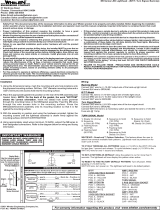
To +VDC (fuse @ 2A)..............RED
To Chassis Ground.............BLACK
For Synchronization.........YELLOW
Connect YELLOW wires of all heads
together for synchronization
(All heads must be set at the same pattern)
For Simultaneous or Alternating Flash:
1. Apply +VDC to RED and YELLOW wires simulta-
neously to enter Grouping mode; lighthead will display
short (single or double) flashes:
Single flash = Group1 Double flash = Group2
2. Remove YELLOW wire from +VDC and momentarily apply to +VDC
to change Groups: Heads in the same Group flash together.
Group1 Heads alternate with Group2 Heads.
3. Disconnect power to save and exit Grouping mode.
For Flash Patterns:
Momentarily apply +VDC to YELLOW wire:
once for next pattern
quickly three times for FP#1
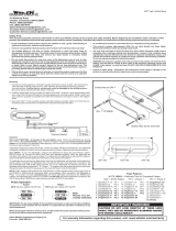
Light Assembly Installation
NOTE: Lighthead mounting
location may vary depending
on the design of the vehicle
light assembly.
1Random
2Steady
3Single
4Mega
5Double
6Triple
7Quad
8Quint
9Ultra
10 Single-Quad
11 Single H/L
12
Flash Patterns
FP#
Single-Triple-Quint
WARNING: DO NOT cover the heatsink with silicone.
This may cause damage to the product and void the warranty.
1. Remove the Corner/Head/Tail light from the vehicle.
2. Select a location to mount the lighthead.
3. Drill an 1 inch diameter cut-out on the light assembly.
4. Insert the lighthead through the double-sided adhesive foam and the cut-out then
press firmly for 1 minutes. (Please ensure that the surface is cleaned thoroughly with
alcohol before mounting.)
5. Apply silicone (user-supplied) for better seal.
OPERATIONS
Mounting
screw holes *
Ø 1” Cut-out
Sheet metal
screw *
Double-sided
adhesive foam
VEHICLE
LIGHT
ASSEMBLY
* Not applicable when mounting with
Double-sided Adhesive Foam
NOTE: Avoid from multiple mount and removal
of the bezel to prevent loose fit.
Bezel Mount Installation
NOTE: Make sure to use the foam when mounting the lighthead.
1. Use the mounting foam to mark wire and screw holes before drilling.
2. Carefully drill marked holes accordingly.
3. Insert lighthead wires through the mounting foam and into the wire hole.
4. Secure the lighthead with supplied sheet metal screws.
5. Mount the snap-on bezel onto the lighthead.
BEZEL REMOVAL
Press
Press
Lift
Apply pressure on both sides
marked with triangle.
Lift the bezel to remove.
Mounting screw holes
VEHICLE
MOUNTING
SURFACE
1.28” (32.5mm)
Foam
Mounting
Bezel
Lighthead
Sheet metal
screw
  • Page 1 1
  • Page 2 2

Cell2 160607M53 User manual

Type
User manual

Cell2 160607M53 features multiple synchronization functions, enabling grouping and alternating flash patterns for enhanced visibility. With 12 distinct flash patterns, including random, steady, single, double, triple, quad, quint, ultra, single-quad, single H/L, and single-triple-quint, you can customize your lighting display to suit your needs. The device also offers simultaneous or alternating flash operation, allowing for versatile signaling options.

Ask a question and I''ll find the answer in the document

Finding information in a document is now easier with AI