Page is loading ...

XTLtouch™ International Series
Installation Guide


TABLE OF CONTENTS
About the XTLtouchINT ....... 1
Install the XTLtouchINT ........2
Wall Mount (XTLtouch) ................... 2
Desk Stand (XTLtouchUSB) .......... 2
Wall Mount .............................3
Mount the Backplate ........................3
Wire for Power .................................... 5
Desk Stand..............................8
Install the Desk Stand Legs ...........8
Power the XTLtouchINT ..................9
Additional Information ....... 10
Secondary Power Supply ............. 10
Replace the Battery ........................ 10
Update Panel Firmware ................. 12
Add a Custom Dealer Logo .......... 13
Add Dealer Info ................................. 13
Accessories ............................ 13
Transformer ......................................... 13
Batteries .............................................. 13
Certifications .........................14
FCC .........................................15
Industry Canada....................17

Digital Monitoring Products | XTLtouchINT Installation Guide
1
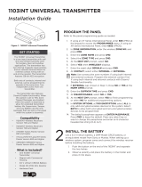
ABOUT THE XTLtouchINT™
The XTLtouchINT oers flexible features and functionality. It contains an XTLplus
control panel with an integrated graphic touchscreen keypad, providing one
device to control and operate a system. The XTLtouchINT has an LTE cellular
communicator pre-installed for cellular use. The XTLtouchINT can be mounted to
a wall or can be used for tabletop use. The XTLtouchINT provides the following
features:
▶5” graphic touchscreen screen
▶Three-part housing (cover, base, and backplate)
▶On-board proximity reader for DMP, HID, and Farpointe credentials
▶On-board Wi-Fi
▶Z-Wave Plus™ support
▶800 mAh battery backup
▶Two-way communication using 868 MHz frequency hopping spread-
spectrum technology
▶1100INT Series Wireless support
▶Wall and Case Tamper

INSTALL THE XTLtouchINT
Wall Mount (XTLtouchINT)
For wall mount installations, use the included backplate to mount the
XTLtouchINT to a wall.
Note: Install the XTLtouchINT near a wall outlet for the plug-in power supply.
The power supply should be located within 100 feet of the XTLtouchINT using
22 AWG wire.
Desk Stand (XTLtouchINTUSB)
For desk stand installations, use the included legs for tabletop use.
Digital Monitoring Products | XTLtouchINT Installation Guide 2

Digital Monitoring Products | XTLtouchINT Installation Guide
3
WALL MOUNT
Mount the Backplate
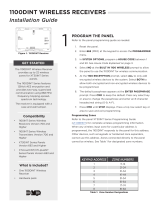
1. Press the tab and remove the backplate from the XTLtouchINT.
See Figure 3.
1
Figure 3: Removing the Backplate
Backplate
Tab

Digital Monitoring Products | XTLtouchINT Installation Guide 4
2. Use the level and the included #6 screws to mount the backplate to the
wall. See Figure 4 for mounting hole locations.
Tamper
Figure 4: Mounting Hole Locations
Level

Digital Monitoring Products | XTLtouchINT Installation Guide
5
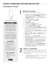
Wire for Power
See Figure 5 for wire routing instructions before wiring the XTLtouchINT for
power.
1. Connect the XTLtouchINT +DC terminal to the positive terminal on
the power supply.
2. Connect the XTLtouchINT -DC terminal to the negative terminal on
the power supply.
3. Plug the power supply into a 120 VAC 50 Hz dedicated outlet that’s
not controlled by a switch.
4. Replace the XTLtouchINT on the mounted backplate.
5. Insert the included set screw to secure the XTLtouchINT to the
mounted backplate. See Figure 6.
2

Digital Monitoring Products | XTLtouchINT Installation Guide 6
- 12V +
Figure 5: Routing Wires
Power Supply
Mounted Backplate
DC terminals
DC terminals

Digital Monitoring Products | XTLtouchINT Installation Guide
7
Figure 6: Securing the XTLtouchINT
with the Set Screw

Digital Monitoring Products | XTLtouchINT Installation Guide 8
DESK STAND
Install the Desk Stand Legs
1. Insert one leg into the holes in the back of the XTLtouchINT.
2. Slide the leg upwards until the leg firmly snaps into place. Repeat
steps 1 and 2 to install the other leg. See Figure 7.
1
Figure 7: Connecting the Desk Stand Legs

Digital Monitoring Products | XTLtouchINT Installation Guide
9
Power the XTLtouchINT
1. Plug the micro USB end of the cable into the back of the keypad.
2. If desired, insert the cable into the strain relief to secure the
XTLtouchINT to its power source. See Figure 8.
3. Plug the other end of the cable into the transformer.
4. Plug the power supply into a 120 VAC 50 Hz dedicated outlet not
controlled by a switch. Use the wall strap to secure the transformer to
the wall.
2
Figure 8: Strain Relief Option
Strain Relief

Digital Monitoring Products | XTLtouchINT Installation Guide 10
ADDITIONAL INFORMATION
SECONDARY POWER SUPPLY
The XTLtouchINT’s 800 mAh rechargeable standby battery is used to provide
four hours of battery power when DC power is not available. The battery is
intended for back power only and should not operate the panel on a daily basis.
If the battery is low or not plugged into the battery connector, a low battery
condition is indicated by the panel. If a 24 hour standby battery is needed,
connect a 4800 mAh battery.
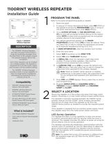
Replace the Battery
1. Remove the backplate from the XTLtouchINT.
2. Unplug the battery and remove it from the base.
3. Place the new battery in the same location and secure it with the included
adhesive. See Figure 9.
4. Plug in the new battery.
5. Replace the backplate.

Digital Monitoring Products | XTLtouchINT Installation Guide
11
3.8 V 4800 mAh Rechargeable Battery
(required for 24 hour standby)
3.8 V 800 mAh
Rechargeable
Battery
Figure 9: Replacing the Battery

Digital Monitoring Products | XTLtouchINT Installation Guide 12
Update Panel Firmware
1. Log in to dmpdealeradmin.com.
2. Navigate to a customer and select their account number.
3. Click Remote Update located in the side menu.
4. Click Update System.
For more details, refer to Dealer Admin Help.
Add a Custom Dealer Logo
To add a custom dealer logo, remove the backplate. Insert a Micro SD card
containing the logo file into the keypad slot with the gold pins facing you. Select
ADD to upload the file. At ADDING LOGO SURE?, select YES. If the upload was
successful, ADDING LOGO COMPLETED is displayed.
Add Dealer Info
To include information about the dealer when the custom logo is pressed on the
home screen, select ADD. The keypad displays ADDING INFO SURE?. Press YES
to proceed. ADDING INFO COMPLETED displays to confirm a successful upload.
Press and release the Micro SD card to eject it from the XTLtouchINT.

Digital Monitoring Products | XTLtouchINT Installation Guide
13
ACCESSORIES
Transformer
372-500-W 12 VDC Nominal Power Supply (wall mount)
371-1000U-W Replacement 1 Amp USB Transformer and Cable (desk stand)
Batteries
XTLTOUCH4800/8 RPLCMNT 4800MAH BATT XTLTOUCH
XTLTOUCH800/8 RPLCMNT 800MAH BATT XTLTOUCH

Digital Monitoring Products | XTLtouchINT Installation Guide 14
Intertek (ETL) Listed
EN 50130-5:2011 Alarm systems. Environmental test methods
EN 50131-1:2006+A1:2009 Alarm systems. Intrusion and hold-up systems. System requirements.
EN 50131-3:2009 Alarm systems. Intrusion and hold-up systems. Control and indicating
equipment.
EN 50131-5-3:2017 Alarm Systems Intrusion Systems. Requirements for Interconnections
Equipment using Radio Frequency
Techniques
EN 50131-5-3:2017 Alarm Systems Intrusion Systems. Requirements for Interconnections
Equipment using Radio Frequency
Techniques.
EN 50136-1:2012 Alarm systems. Alarm transmission systems and equipment. General
requirements for alarm transmission
systems.
EN 50136-2:2013 Alarm systems. Alarm transmission systems and equipment. Requirements
for Supervised Premises Transceiver (SPT).
CERTIFICATIONS

Digital Monitoring Products | XTLtouchINT Installation Guide
17

Digital Monitoring Products | XTLtouchINT Installation Guide 18

LT-1788INT 20342 © 2020 Digital Monitoring Products, Inc.
/