Page is loading ...

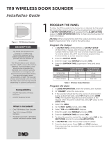
XTLtouch
TM
Series
Installation Guide


TABLE OF CONTENTS
About the XTLtouch .............. 1
Install the XTLtouch ..............2
Wall Mount (XTLtouch) ................... 2
Desk Stand (XTLtouchUSB) .......... 2
Wall Mount .............................3
Mount the Backplate ........................ 3
Wire for Power .................................... 5
Desk Stand..............................8
Install the Desk Stand Legs ........... 8
Power the XTLtouch .........................9
Additional Information ....... 10
Secondary Power Supply ............... 10
Replace the Battery ........................ 10
Accessories ............................12
Transformer ......................................... 12
Batteries .............................................. 12
Certifications ......................... 13
FCC .........................................14
Industry Canada....................16

Digital Monitoring Products | XTLtouch Installation Guide1
ABOUT THE XTLtouch™
The XTLtouch oers flexible features and functionality. It contains an XTLplus
control panel with an integrated graphic touchscreen keypad, providing one
device to control and operate a system. The XTLtouch has an LTE cellular
communicator pre-installed for cellular use. The XTLtouch can be mounted to
a wall or can be used for tabletop use. The XTLtouch provides the following
features:
▶ 5” graphic touchscreen screen
▶ Three-part housing (cover, base, and backplate)
▶ On-board proximity reader for DMP, HID, and Farpointe credentials
▶ On-board Wi-Fi
▶ Z-Wave Plus™ support
▶ 800 mAh battery backup
▶ Two-way communication using 900 MHz frequency hopping spread-
spectrum technology
▶ 1100 Series Wireless support

INSTALL THE XTLtouch
Wall Mount (XTLtouch)
For wall mount installations, use the included backplate to mount the XTLtouch
to a wall.
Note: Install the XTLtouch near a wall outlet for the plug-in power supply.
The power supply should be located within 100 feet of the XTLtouch using
22 AWG wire.
Desk Stand (XTLtouchUSB)
For desk stand installations, use the included legs for tabletop use.
Digital Monitoring Products | XTLtouch Installation Guide 2

Digital Monitoring Products | XTLtouch Installation Guide3
WALL MOUNT
Mount the Backplate
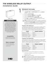
1. Press the tab and remove the backplate from the XTLtouch.
See Figure 3.
1
Figure 3: Removing the Backplate
Backplate
Tab

Digital Monitoring Products | XTLtouch Installation Guide 4
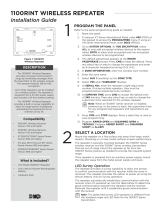
2. Use the level and the included #6 screws to mount the backplate to the
wall. See Figure 4 for mounting hole locations.
Figure 4: Mounting Hole Locations
Level

Digital Monitoring Products | XTLtouch Installation Guide5
Wire for Power
See Figure 5 for wire routing instructions before wiring the XTLtouch for
power.
1. Connect the XTLtouch +DC terminal to the positive terminal on the
power supply.
2. Connect the XTLtouch -DC terminal to the negative terminal on the
power supply.
3. Plug the power supply into a 120 VAC 60 Hz dedicated outlet that’s
not controlled by a switch.
4. Replace the XTLtouch on the mounted backplate.
5. Insert the included set screw to secure the XTLtouch to the mounted
backplate. See Figure 6.
2

Digital Monitoring Products | XTLtouch Installation Guide 6
- 12V +
Figure 5: Routing Wires
Power Supply
Mounted Backplate
DC terminals
DC terminals

Digital Monitoring Products | XTLtouch Installation Guide7
Figure 6: Securing the XTLtouch
with the Set Screw

Digital Monitoring Products | XTLtouch Installation Guide 8
DESK STAND
Install the Desk Stand Legs
1. Insert one leg into the holes in the back of the XTLtouch.
2. Slide the leg upwards until the leg firmly snaps into place. Repeat
steps 1 and 2 to install the other leg. See Figure 7.
1
Figure 7: Connecting the Desk Stand Legs

Digital Monitoring Products | XTLtouch Installation Guide9
Power the XTLtouch
1. Plug the micro USB end of the cable into the back of the keypad.
2. If desired, insert the cable into the strain relief to secure the XTLtouch
to its power source. See Figure 8.
3. Plug the other end of the cable into the transformer.
4. Plug the power supply into a 120 VAC 60 Hz dedicated outlet not
controlled by a switch. Use the wall strap to secure the transformer to
the wall.
2
Figure 8: Strain Relief Option
Strain Relief

Digital Monitoring Products | XTLtouch Installation Guide 10
ADDITIONAL INFORMATION
SECONDARY POWER SUPPLY
The XTLtouch’s 800 mAh rechargeable standby battery is used to provide four
hours of battery power when DC power is not available. The battery is intended
for back power only and should not operate the panel on a daily basis.
If the battery is low or not plugged into the battery connector, a low battery
condition is indicated by the panel. If a 24 hour standby battery is needed,
connect a 4800 mAh battery.
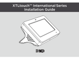
Replace the Battery
1. Remove the backplate from the XTLtouch.
2. Unplug the battery and remove it from the base.
3. Place the new battery in the same location and secure it with the included
adhesive. See Figure 9.
4. Plug in the new battery.
5. Replace the backplate.

Digital Monitoring Products | XTLtouch Installation Guide11
3.8 V 4800 mAh Rechargeable Battery
(required for 24 hour standby)
3.8 V 800 mAh
Rechargeable
Battery
Figure 9: Replacing the Battery

Digital Monitoring Products | XTLtouch Installation Guide 12
ACCESSORIES
Transformer
372-500-W 12 VDC Nominal Power Supply (wall mount)
371-1000U-W Replacement 1 Amp USB Transformer and Cable (desk stand)
Batteries
XTLTOUCH4800/8 RPLCMNT 4800MAH BATT XTLTOUCH
XTLTOUCH800/8 RPLCMNT 800MAH BATT XTLTOUCH

Digital Monitoring Products | XTLtouch Installation Guide13
FCC Wireless Receiver and Z-Wave Approvals
FCC ID: CCKPC0199
IC: 5251A-PC0199
FCC Wi-Fi Network Approvals
FCC ID: VW4-ATWINC1500
IC: 20266-WINC1500PB
FCC LTE Cellular Communicators
LTE FCC Part 15 ID: R17ME910C1NV
Intertek (ETL) Listed
ANSI/UL 985 Household Fire
ANSI/UL 1023 Household Burglar
ANSI/UL 1610 Central Station Burglar
ANSI/UL 1635 Digital Burglar
CERTIFICATIONS

Digital Monitoring Products | XTLtouch Installation Guide 14
This device complies with Part 15 of the FCC Rules. Operation is subject to the
following two conditions:
1. This device may not cause harmful interference, and
2. This device must accept any interference received, including interference
that may cause undesired operation.
Changes or modifications made by the user and not expressly approved by the
party responsible for compliance could void the user’s authority to operate the
equipment.
Note: This equipment has been tested and found to comply with the limits
for a Class B digital device, pursuant to part 15 of the FCC Rules. These limits
are designed to provide reasonable protection against harmful interference
in a residential installation. This equipment generates, uses and can radiate
radio frequency energy and, if not installed and used in accordance with
the instructions, may cause harmful interference to radio communications.
However, there is no guarantee that interference will not occur in a particular
installation. If this equipment does cause harmful interference to radio or
television reception, which can be determined by turning the equipment o
and on, the user is encouraged to try to correct the interference by one or
more of the following measures:
FCC

Digital Monitoring Products | XTLtouch Installation Guide15
• Reorient or relocate the receiving antenna.
• Increase the separation between the equipment and receiver.
• Connect the equipment into an outlet on a circuit dierent from that to
which the receiver is connected.
• Consult the dealer or an experienced radio/TV technician for help.
Note: For listed residential fire and burglary applications, wire runs
connected to the XTLtouch terminal block must remain in the same room
within 98.5 feet (30 meters.)

Digital Monitoring Products | XTLtouch Installation Guide 16
This device complies with Industry Canada Licence-exempt RSS standard(s).
Operation is subject to the following two conditions:
1. This device may not cause interference, and
2. This device must accept any interference, including interference that may
cause undesired operation of the device.
Le présent appareil est conforme aux CNR d’Industrie Canada applicables
aux appareils radio exempts de licence. L’exploitation est autorisée aux deux
conditions suivantes:
1. l’appareil ne doit pas produire de brouillage, et
2. l’utilisateur de l’appareil doit accepter tout brouillage radioélectrique
subi, même si le brouillage est susceptible d’en compromettre le
fonctionnement.
INDUSTRY CANADA

LT-1788 18373 © 2018 Digital Monitoring Products, Inc.
/