Page is loading ...

1103INT UNIVERSAL TRANSMITTER
Installation Guide
GET STARTED
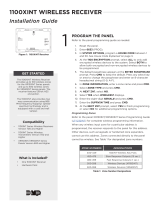
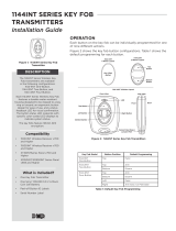
The 1103INT Universal Transmitter
is a two-input transmitter with wall
and case tamper typically used
for burglary door and window
applications. The transmitter has
two internal magnetic reed switches
and an onboard terminal block for
external contact wiring with an
end-of-line resistor. The transmitter
features 128-bit AES encryption.
Both sets of contacts, internal and
external, can be programmed to
operate at the same time. Two
independent zones from one
transmitter.
The transmitter also features
Disarm/Disable functionality. When
this option is set to YES, Zone
Tripped Messages are disabled
when the system is disarmed to
allow for extended transmitter
battery life. Supervision, Tamper,
and Low Battery are the only
messages that are sent to the panel
when the system is disarmed.
Compatibility
• 1100XINT Wireless Receivers
Version 700 and Higher
• 1100DINT Wireless Receivers
Version 700 and Higher
• XT30INT Series Panels Version
693 and Higher
• XTLtouchINT/XTLplusINT Series
Panels Version 693 and Higher
• XR150INT/XR550INT Series
Panels Version 693 and Higher
What is Included?
• One 1103INT Universal
Transmitter
• Magnet with Commercial
Housing
• 3.0 V Lithium CR123A Battery
• Model 312 470K EOL Resistor
• Hardware Pack
1PROGRAM THE PANEL
Refer to the panel programming guide as needed.
1. If using an XT Series International Panel, enter 665 (PRO) at
the keypad to access the PROGRAMMER menu. If using an
XR Series International Panel, enter 6653 (PROG).
2. In ZONE INFORMATION, enter the wireless ZONE NO: and
press CMD.
3. Enter the ZONE NAME and press CMD.
4. Select the ZONE TYPE and press CMD.
5. At the NEXT ZN? prompt, select NO.
6. Select YES when WIRELESS? displays.
7. Enter the eight-digit SERIAL# and press CMD.
8. At CONTACT, select either INTERNAL or EXTERNAL.
Note: Use consecutive zone numbers if using both internal
and external contacts. Program the external contact first
if using both internal and external contacts with Disarm/
Disable functionality.
9. If EXTERNAL was chosen in Step 7, chose NO or YES at the
NORM OPEN prompt.
10. Enter the SUPRVSN TIME and press CMD.
11. At DISARM DISABLE, select NO or YES.
12. At the NEXT ZN? prompt, select YES to finish programming
or select NO for additional programming options.
13. In SYSTEM OPTIONS, at 1100 ENCRYPTION, select ALL to
only add encrypted wireless devices to the system. Select
BOTH to allow both encrypted and non-encrypted wireless
devices to be programmed.
14. The default passphrase appears at ENTER PASSPHRASE.
Press CMD to keep the default. Press any select key or
area to change the passphrase and enter an 8-character
hexadecimal string (0-9, A-F).
INSTALL THE BATTERY
2Use a 3.0 V lithium battery, a DMP Model CR123 battery, or
an equivalent model from Sony or Murata. When setting up a
wireless system, program zones and connect the wireless receiver
before installing the battery.
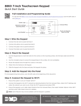
1. Push the button on the end of the 1103INT and separate
the two halves.
2. Observe polarity and place the battery in the holder and
press it into place.
Figure 1: 1103INT Universal Transmitter

2 1103INT INSTALLATION GUIDE | DIGITAL MONITORING PRODUCTS
MOUNT THE 1103INT TRANSMITTER
Caution: Do not mount on ferromagnetic surfaces.
Mount the Transmitter
1. Remove the battery.
2. Hold the transmitter in place with the magnetic reed switch
closest to where the magnet will be mounted, See Figure 2.
Ensure the transmitter and the magnet are no more than 1” (2.54
cm) apart.
3. Place the supplied #4 screw into the mounting hole and secure
the transmitter to the surface.
4. Replace the battery.
5. Snap the transmitter cover back onto the base.
Mount the Magnet
1. Place and hold the magnet directly on the door closest to the
magnetic reed switch, no more than 1” (2.54 cm) apart from the
transmitter. See Figure 3.
2. Use the provided #4 screws to mount the magnet.
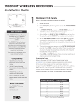
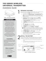
Wiring and Connecting Contacts
When connecting an external contact to the terminal block in burglary applications, DMP recommends using
18 or 22 AWG unshielded wire. Do not use twisted pair or shielded wire. Locate a contact within 100 ft (30.5
meters) of the 1103INT. Connect the contact as normally open (N/O) or normally closed (N/C) with the 470K
end-of-line resistor. See Figure 4.
Note: The Normally Open YES NO option in the panel wireless zone programming has no eect on the
transmitter operation when using the 470K end-of-line resistor.
4
3The 1103INT provides a survey LED that allows one person to confirm communication with the wireless receiver
or panel while the cover is removed.
1. Hold the 1103INT in the exact desired location.
2. Press the tamper switch to send data to the panel and determine if communications is confirmed or
faulty.
Confirmed: If communication is confirmed, for each press or release of the tamper switch the LED blinks
immediately on and immediately o.
Faulty: If communication is faulty, the LED remains on for about 8 seconds or flashes multiple
times in quick succession. Relocate the 1103INT or the wireless receiver until the LED confirms clear
communication.
SELECT A LOCATION
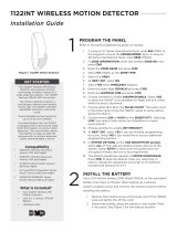
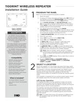
Figure 2: Transmitter Components
Survey LED
Mounting Hole
Magnetic
Reed Switches
Mounting Hole
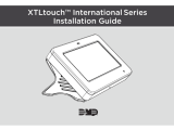
PLACEMENT OPTIONS
Figure 3: Placement Options
EXTERNAL CONTACTS
Parallel for N/O
Series for N/C
External Contact
Terminal Block
1103
Door
Window
External
Contact
Magnet
Program an internal
contact as the next
consecutive zone.
Program an
external contact
as the first
zone.
Figure 4: Contact Terminal Block Wiring

1103INT INSTALLATION GUIDE | DIGITAL MONITORING PRODUCTS 3
5TEST THE 1103INT TRANSMITTER
After the transmitter has been installed, test to confirm that it is communicating reliably with the panel. Use
the Tech APP™ to perform a Wireless Check-in Test on the system or complete the following steps to perform
a Check-in Test from a keypad that is connected to the panel.
1. At the keypad for XT Series panels, enter 8144 (WALK). At the keypad for XR Series panels, enter 814
(WAL). Select WLS.
2. If the 1103INT fails to check in at the keypad, relocate the wireless device, receiver, or panel.
ADDITIONAL INFORMATION
Using XT30INT/XTLplusINT/XTLtouchINT Series Panels
The 1103INT is designed for the XR150INT/XR550INT Series panels. However, it can be used with the XT30INT/
XTLplusINT/XTLtouchINT Series panels.
When used with XT panels, the tamper indication is sent through the internal contact zone only. When using the external
contact, the internal contact must also be programmed in a separate zone to provide tamper indication. The supplied
magnet must be mounted next to the 1103INT internal contact to restore the zone and allow the tamper switch to have
priority.
Replace the Battery
1. Push the button on the end of the transmitter and separate the two halves.
2. Remove the old battery and dispose of it properly.
3. Observing polarity, place the new battery in the holder and press into place.
Note: Use only 3.0 V lithium CR123A batteries.
4. Place the cover back onto the 1103INT and snap back into place.
Sensor Reset to Clear LOBAT
When the battery needs to be replaced, a LOBAT message will display on the keypad. Once the battery is replaced, a
sensor reset is required at the system keypad to clear the LOBAT message.
1. On a Thinline keypad, press and hold “2” for two seconds. On a touchscreen keypad press RESET.
2. Enter your user code if required.
3. The keypad displays SENSORS OFF followed by SENSORS ON.
COMPLIANCE SPECIFICATIONS
Reed Switch Distances
Break (Alarm)
X: 18.5 mm
Y: 41.5 mm
Z: 35.5 mm
Make (Restore)
X: 14.5 mm
Y: 39.0 mm
Z: 19.5 mm

Designed, engineered, and
manufactured in Springfield, MO
using U.S. and global components.
LT-0702INT 1.01 22133
INTRUSION • FIRE • ACCESS • NETWORKS
2500 North Partnership Boulevard
Springfield, Missouri 65803-8877
800.641.4282 | DMP.com
© 2023
1103INT
UNIVERSAL
TRANSMITTER
Specifications
Security Grade 2
Environmental Class II
Operating Temperature 0°C - 49°C
32°F - 120°F
Relative Humidity 80%
Weight .091kg
Battery
Life Expectancy 5 years (normal operation)
Type 3.0 V lithium CR123A
Low Battery 2.4 VDC or less
Frequency Range 863-869 MHz
Housing Material Flame retardant ABS
Dimensions 3.3”L x 1.6”W x 1.2”H
8.4 L x 4.06 W x 3.05 H cm
Color White
Accessories
CR123 3.0 V Lithium Battery
Patents
U. S. Patent No. 7,239,236
International Certificates
Intertek (ETL)
EN 50130-4:2011 EMC - Product Family Standard.
Immunity Requirements for
Components of Fire, Intruder, and
Social Alarm Systems
EN 50130-5:2011 Alarm Systems. Environmental Test
Methods
EN 50131-1:2006+A1;A2 Alarm Systems. Intrusion and Hold-
up Systems. System Requirements
EN 50131-3:2009 Alarm Systems. Intrusion and Hold-
up Systems. Control and Indicating
Equipment
EN 50131-2-6:2008 Alarm Systems. Intrusion and Hold-
up Systems. Intrusion Detectors.
Requirements for Opening Contacts
(Magnetic)
EN50131-5-3:2005+A1: Alarm Systems. Intrusion systems.
2008 Requirements for Interconnections
Equipment using Radio Frequency
Techniques
EN 61000-3-2:2009+A1;A2 Limits - Limits for Harmonic Current
Emissions (Equipment Input Current
less than or equal to 16A per Phase)
EN 61000-3-3:2013 Limits - Limitation of Voltage
Changes, Voltage Fluctuations and
Flicker in Public Low-Voltage Supply
Systems, for Equipment With Rated
Current less than or equal to 16A
per Phase and Not Subject to
Conditional Connection
EN 61000-6-4:2018 Generic Standard - Emission
Standard for Industrial
Environments
/