Digital Monitoring Products 1128 International Wireless Glassbreak Detector Installation & Programming Guides
- Type
- Installation & Programming Guides
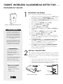
**Digital Monitoring Products 1128 International Wireless Glassbreak Detector **is a fully-supervised wireless sensor device used to detect glass breakage via shock and high-frequency audio detection within a 20ft radius of the device. This device can be used to detect break-ins or other security breaches, when mounted to ceilings or opposing walls. The device transmits data using 128-bit AES encryption for added security over a frequency range of 863-869 MHz.
**Digital Monitoring Products 1128 International Wireless Glassbreak Detector **is a fully-supervised wireless sensor device used to detect glass breakage via shock and high-frequency audio detection within a 20ft radius of the device. This device can be used to detect break-ins or other security breaches, when mounted to ceilings or opposing walls. The device transmits data using 128-bit AES encryption for added security over a frequency range of 863-869 MHz.


-
 1
1
-
 2
2
-
 3
3
-
 4
4


Digital Monitoring Products 1128 International Wireless Glassbreak Detector Installation & Programming Guides
- Type
- Installation & Programming Guides
**Digital Monitoring Products 1128 International Wireless Glassbreak Detector **is a fully-supervised wireless sensor device used to detect glass breakage via shock and high-frequency audio detection within a 20ft radius of the device. This device can be used to detect break-ins or other security breaches, when mounted to ceilings or opposing walls. The device transmits data using 128-bit AES encryption for added security over a frequency range of 863-869 MHz.
Ask a question and I''ll find the answer in the document
Finding information in a document is now easier with AI
Related papers
-
 Digital Monitoring Products 1122 International Wireless Motion Detector Installation & Programming Guides
-
 Digital Monitoring Products 1100XINT Wireless Receiver Installation & Programming Guides
-
 Digital Monitoring Products 1100DINT Wireless Receiver Installation & Programming Guides
-
 Digital Monitoring Products 1121 User guide
-
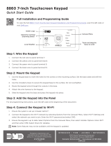 Digital Monitoring Products 8860 Series 7-Inch Touchscreen Keypad Quick start guide
-
 Digital Monitoring Products 9862 Wireless Graphic Touchscreen Key Pad Installation guide
-
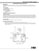 Digital Monitoring Products 1100X-WINT Wireless Receiver Installation guide
-
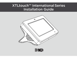
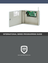 Digital Monitoring Products XR150/XR550 International Installation & Programming Guides
-
 Digital Monitoring Products 1125 User guide
-
 Digital Monitoring Products 1132 Wireless Recessed Door Contact Installation guide


Other documents
-
 DMP Electronics 1128 Installation guide
-
DMP 1100 Series User guide
-
Honeywell FG-701 User manual
-
DMP XT Series User guide
-
Interlogix ShatterPro Glassbreak Sensors (60-873-95/NX-488) Installation guide
-
ADEMCO FlexGuard 5853 Installation guide
-
Crow FW2-GBD Installation guide
-
Honeywell FlexGuard FG-1625SN V-Plex Installation guide
-
Bosch Appliances 8-Dec User manual
-
Inovonics EN1247 Installation guide
