Page is loading ...

1100RINT WIRELESS REPEATER
Installation Guide
GET STARTED
RF RX
RF TX
PANEL RX
PANEL TX
WALL
TAMPER
ENABLE
DISABLE
STATUS
PWR
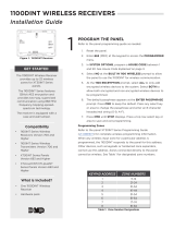
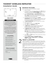
The 1100RINT Wireless Repeater
provides increased communication
range by forwarding messages
from the transmitter to the wireless
receiver. The repeater features 128
bit-AES encryption.
Up to three repeaters can be
installed on a wireless system.
The repeater is powered from a 12
VDC power supply and includes a
24-hour battery backup.
The 1100RINT Wireless Repeater
provides a built-in survey
capability to allow for single-
person installations, eliminating the
requirement for an external survey
kit.
Compatibility
• 1100INT Wireless Receivers
Version 700 and Higher
• 1100XINT Wireless Transmitters
Version 700 and Higher
• XT30INT Series Panels Version
693 and Higher
• XTLtouchINT/XTLplusINT Series
Panels Version 693 and Higher
• XR150INT/XR550INT Series
Panels Version 693 and Higher
What is Included?
• One 1100RINT Repeater
• One Lithium Polymer
Rechargeable Battery
• Hardware Pack
1PROGRAM THE PANEL
Refer to the panel programming guide as needed.
1. Reset the panel.
2. If using an XT Series International Panel, enter 665 (PRO) at
the keypad to access the PROGRAMMER menu. If using an
XR Series International Panel, enter 6653 (PROG).
3. Go to SYSTEM OPTIONS. At 1100 ENCRYPTION, select ALL
to only add encrypted wireless devices to the system. Select
BOTH to allow both encrypted and non-encrypted wireless
devices to be programmed.
4. The default passphrase appears at the ENTER PASSPHRASE
prompt. Press CMD to keep the default. Press any select key
or area to change the passphrase and enter an 8-character
hexadecimal string (0-9, A-F).
5. In ZONE INFORMATION, enter the wireless zone number.
6. Enter the ZONE NAME.
7. Select AUX 1 (auxiliary 1) as the ZONE TYPE.
8. At WIRELESS? select YES.
9. At SERIAL NO:, enter the repeater’s eight-digit serial
number. If using multiple repeaters, they must be
programmed as sequential zone numbers.
10. At SUPRVSN TIME, press CMD to accept the default time
of 240 minutes. Press any select key or area to change the
supervision time required for the wireless repeater.
Note: When an 1100INT Series receiver is installed, powered
up, or the panel is reset, the supervision time for any
programmed repeaters and transmitters are reset.
11. Program ARMED OPEN and DISARMED OPEN as TROUBLE
so that a power trouble sends a trouble alert.
12. Program ARMED SHORT and DISARMED SHORT as ALARM
so that a tamper sends an alarm alert.
13. Press CMD until STOP displays. Press a top row select key or
area to save programming.
Figure 1: 1100RINT Repeater

2 1100RINT INSTALLATION GUIDE | DIGITAL MONITORING PRODUCTS
MOUNT THE 1100RINT REPEATER
The repeater is equipped with a case and wall tamper. When the housing cover is removed, the case tamper
activates and the receiver sends a tamper trouble to the panel. To enable the tamper, see the following steps.
A two-position header is provided to disable the wall tamper. To disable the wall tamper, place the jumper
across the two pins of the header.
1. With the cover already removed, remove
the PCB from the housing to access the
tamper and mounting holes.
2. Mount the receiver on a flat surface using
the supplied screws. See Figure 2 for
mounting hole locations.
3. Use one of the provided screws to anchor
the housing in the wall tamper screw hole.
4. Snap the PCB back into the housing
attached to the wall. Observe LED
operation.
3
2Mount the repeater away from large metal objects. Mounting on or near metal surfaces impairs performance.
The repeater should be mounted between the 1100INT Series wireless receiver and the 1100INT Series wireless
transmitters that are out of range. Mount the repeater as far from the 1100INT Series receiver as needed to
provide the required system range.
If the repeater is powered from an auxiliary power supply, mount the repeater away from the metal power
supply enclosure.
LED Survey Option
The repeater provides a survey capability to allow one person to confirm communication with the receiver
while the cover is removed. The repeater provides the option to power up using the lithium battery only for
survey operation.
The repeater automatically establishes communication with the receiver when it’s powered up. Use the table
below to determine good communication between the repeater and the receiver. Relocate the repeater until it
establishes good communication with the receiver.
Note: The green/red LED operation is dierent from the standard single red LED flash for the 1100INT
Series transmitters.
SELECT A LOCATION
LED SURVEY OPERATION
Status Operation
GOOD
Green indicates that reliable communication is established with the receiver.
Reliable communication is defined as the last five messages sent by the
repeater have been acknowledged immediately by the receiver. A message
can be sent by pressing or releasing the tamper switch on the repeater.
BAD
Red indicates that the repeater has not established reliable communication
with the receiver. Communication is not considered reliable when the last 5
out of 15 messages sent have not been acknowledged immediately by the
receiver. Messages may still be communicated, however the communication
link between the repeater and the receiver is not optimum. In this case, the
repeater should be relocated until the GOOD LED lights green.
PWR Green indicates that there is power to the repeater.
Table 1: LED Survey Operation
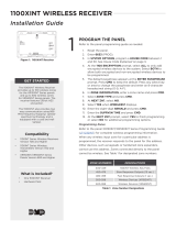
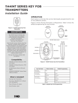
Tamper Puck
Figure 2: Inside of the 1100RINT Housing
Mounting
Hole
Battery

1100RINT INSTALLATION GUIDE | DIGITAL MONITORING PRODUCTS 3
4POWER THE 1100RINT REPEATER
The repeater can be powered from a 12 VDC external power supply such as a DMP model 503INT or an
external DC Plug-In power supply such as the DMP Model 376L. In addition to powering the 1100RINT, the
power supply also charges the back-up battery on the 1100RINT that should be connected at the time of the
installation. If the DC power source is removed, the power failure is indicated as an open condition on the
1100RINT zone.
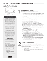
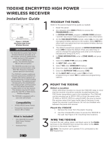
Connect the External Power Supply
1. Observe positive and negative polarity on all connections.
2. Using the 22 AWG wire, connect the DC power terminal block
to the DC terminal on the 503INT power supply PCB. See
Figure 3.
Connect the External DC Plug-In Power Supply
Use the following steps to connect the model 376 plug-in DC power
supply to the repeater:
1. Connect the black wire with the white stripe to the R (red)
terminal on the 1100RINT.
2. Connect the black wire to the B (black) terminal on the
1100RINT.
3. Plug the power supply into a wall outlet not controlled by a
switch.
Note: The DC plug-in power supply also charges the backup
battery. The 376L plug-in power supply must be located within
100 feet of the repeater using the 22 AWG wire or 250 feet using
18 AWG wire.
ADDITIONAL INFORMATION
Primary Power Loss Indication
When the repeater is used with XT30INT Series and XTLplusINT/XTLtouchINT Series panels, a zone trouble indication
for the repeater zone occurs within three minutes of a loss of primary power.
When used with XR150INT/XR550INT Series panels, as power loss indication is displayed at the keypad as -ACPWR for
the repeater zone. This occurs within three minutes but a zone trouble report to the Central Station receiver is delayed
for one hour.
Replace the Backup Battery
The repeater’s rechargeable battery provides up to 24 hours of backup battery power when AC or DC power is not
available. The battery is intended for backup power only. It should not operate on a daily basis. If the battery is low, or
not plugged into the battery connector, a low battery condition is indicated for the programmed zone.
Use only a DMP replacement battery for the backup battery. Replace the battery every three years. Use the steps below
to remove and install a new backup battery.
Remove the Old Backup Battery
1. Remove the 1100RINT housing cover and remove the PCB from the housing.
2. Disconnect the battery lead connector from the BAT header.
3. Remove the battery from the double sided tape.
Install the New Backup Battery
1. Place the new battery on the 1100RINT housing base and secure it to the double sided tape.
2. Observe polarity and connect the battery lead connector to the BAT header.
3. Replace the housing cover.
RR YGB
+-
503INTPower
Supply
1100RINT DC Power
4-position terminal block
22AWG Wire
12VDC at
5Amps
Figure 3: External Power Supply
R Y G B
Black wire
with white
stripe Black
wire
DC plug-in
power
supply
DC power 4-position
terminal block
Figure 4: DC Plug-In Power Supply

Designed, engineered, and
manufactured in Springfield, MO
using U.S. and global components.
LT-1824INT 1.01 22133
INTRUSION • FIRE • ACCESS • NETWORKS
2500 North Partnership Boulevard
Springfield, Missouri 65803-8877
800.641.4282 | DMP.com
© 2023
1100RINT
WIRELESS REPEATER
Specifications
Security Grade 2
Environmental Class II
Operating Temperature 0°C - 49°C
32°F - 120°F
Relative Humidity 80%
Weight .27kg
Primary Operating Voltage 8.0 to 14.0 VDC, 30 mA
Current Draw 25mA (average), 35mA (peak)
Standby Battery 1100RBAT
Voltage 3.7 VDC
Capacity 800 mAh
Type Lithium Polymer Rechargeable
Standby 24 hours
Frequency Range 863-869 MHz
Housing Material Flame retardant ABS
Dimensions 5.5”L x 3.75”W x 1”H
13.97 L x 9.5 W x 2.5a H cm
Color White
Accessories
1100RBAT800/8 Replacement 800 mAh battery,
Pack of 8
503INT 12 VDC Power Supply
376L Plug-In DC Power Supply
Patents
U. S. Patent No. 7,239,236
International Certificates
Intertek (ETL)
EN 50130-4:2011 EMC - Product Family Standard.
Immunity Requirements for
Components of Fire, Intruder, and
Social Alarm Systems
EN 50130-5:2011 Alarm Systems. Environmental Test
Methods
EN 50131-1:2006+A1;A2 Alarm Systems. Intrusion and Hold-
up Systems. System Requirements
EN 50131-3:2009 Alarm Systems. Intrusion and Hold-
up Systems. Control and Indicating
Equipment
EN50131-5-3:2005+A1: Alarm Systems. Intrusion systems.
2008 Requirements for Interconnections
Equipment using Radio Frequency
Techniques
EN 61000-3-2:2009+A1;A2 Limits - Limits for Harmonic Current
Emissions (Equipment Input Current
less than or equal to 16 A per Phase)
EN 61000-3-3:2013 Limits - Limitation of Voltage
Changes, Voltage Fluctuations and
Flicker in Public Low-Voltage Supply
Systems, for Equipment With Rather
Current less than or equal to 16 A
per Phase and Not Subject to
Conditional Connection
EN 61000-6-4:2018 Generic Standard - Emission
Standard for Industrial
Environments
R Y G B
TO PANEL
/