Page is loading ...

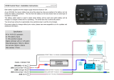
EC500 Power Control System
Issue 2 Page 1 of 19 20
th
December 2011
1 Introduction
This section of the handbook will guide you through the operation of the electrical system.
Further technical details are contained in sections 3 to 6 or in the supporting technical manual available
from www.sargentltd.co.uk
For the safe operation of all electrical equipment within your Leisure Vehicle it is important that you
read and fully understand these instructions. If you are unsure of any point please contact your dealer
/ distributor for advice before use.
The system has a number of key components that you will need to be familiar with before attempting to
use the system, these are:
· The EC500 series Power Supply Unit (PSU) - a combined mains consumer unit and 12V controller
located in the front locker. On some vehicle layouts this unit may be located elsewhere.
· The EC300 or EC480 series Control Panel (CP) - a remotely located user control panel used to turn
circuits on and off and to display battery and water tank information.
· The PX-300 Battery Charger / Power Supply – a separate, air cooled 300 Watt multi-stage power
converter unit that charges the batteries and provides 12V DC power.
· The EM40 Interface Unit - This small unit is located at floor level behind the drivers’ seat. The unit
houses fuses for the fridge, vehicle battery, radio and other systems. It also provides connections
for the optional tow bar harness.
2 Using the System
The PSU is located in the front offside locker in most vehicle layouts.
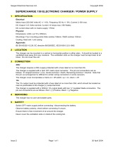
2.1 EC500 Power Supply Unit – Component Layout
Water heater
switch
Space heater
switch
Charger
switch
Reverse polarity
indicator
Residual Current
Device (RCD)
Miniature Circuit
Breakers (MCB’s)
RCD
Test
button
12 Volt DC fuses
(under flap)
Shutdown
switch
Battery
select button
Lights
button
Pump
button
Power
button

EC500 Power Control System
Issue 2 Page 2 of 19 20
th
December 2011
2.2 Activating the System
The EC500 system has a shutdown feature that should be used when the vehicle is in storage or is not
being used for long periods of time. This allows the leisure electronics to be turned off when not
required to save battery power. When in the off state the alarm and tracking system supplies are still
active, most other supplies are turned off.
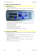
Before using the system please ensure the system shutdown switch is in the on position (button in).
PSU – 12V Controls
The black system shutdown button is shown on the
left. In is on and out is off.
See section 2.5 for a description of the four control
buttons.
2.3 Connecting to the Mains 230V supply and Safety checks
For your safety it is IMPORTANT that you follow these connections instructions each time your Leisure
Vehicle is connected to a mains supply. This section assumes that the system is complete and that a
Leisure battery has been installed (see 3.5).
A) Ensure suitability of the Mains Supply. Your Leisure Vehicle should only be connected to an
approved supply that meets the requirements of BS7671 or relevant harmonised standards. In
most cases the site warden will hold information regarding suitability of supply. If using a generator
you also need to comply with the requirements / instructions supplied with the generator. Please
note that some electronic generators may not be compatible with your leisure system. Further
generator operational information is contained elsewhere in this manual.
B) Switch the PSU internal Power Converter OFF. Locate the green ‘Charger’ power switch on the
PSU and ensure the switch is in the off position (button out) before connection to the mains supply.
C) Connect the Hook-up Lead. Firstly connect the supplied hook-up lead (orange cable with blue
connectors) to the Leisure Vehicle and then connect to the mains supply.
D) Check Residual Current Device operation. Locate the RCD within the PSU and ensure the RCD
is switched on (lever in up position). Press the ‘Test’ button and confirm that the RCD turns off
(lever in down position). Switch the RCD back to the on position (lever in up position). If the test
button failed to operate the RCD see section 3.14.
E) Check Miniature Circuit Breakers. Locate the MCB’s within the PSU (adjacent to the RCD) and
ensure they are all in the on (up) position. If any MCB fails to ‘latch’ in the on position see section
3.14.
F) Turn the PSU ON. Locate the black ‘Shutdown’ button and ensure it is in the on position (press
button to change, button in = on, button out = off). Locate the green ‘Charger’ switch on the PSU
and turn to the on position (press button to change, button in = on, button out = off). The charger
switch will illuminate when turned on.
G) Check correct Polarity. Locate the ‘Reverse polarity’ indicator on the PSU and ensure that the
indicator is NOT illuminated. If the indicator is illuminated see section 3.14. Please note that this
indicator works in conjunction with the charger switch, so will only operate when the charger is on.
H) Check operation of equipment. It is now safe to operate the 12v and 230v equipment.

EC500 Power Control System
Issue 2 Page 3 of 19 20
th
December 2011
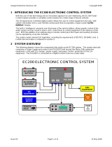
PSU – 230V Controls
Black lever switch, far left – Residual Current Device
(RCD) and main 230V on / off switch.
Yellow button, far left – RCD test button.
Red lever switches, right – 3 x 10A Miniature Circuit
Breakers (MCB).
Red indicator – Reverse polarity warning indicator.
This illuminates when the green charger is turned on
(see below) and the 230V supply polarity is reversed
(see 3.14).
Green push switch – Charger switch, this switch
turns the 12V battery charger on or off. In is on out
is off.
Amber push switch – Space heater switch, this
switch turns the 230V supply to the space heater /
combination heater / central heating system on or
off. In is on out is off.
Clear push switch – Water heater switch, this switch
turns the 230V supply to the separate water heater
on or off. In is on out is off.
Note: If the vehicle contains a combined space &
Water heater then this button is not used.
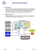
2.4 Control Panel - Component Layout
Depending on your vehicle model and specification the control panel will be either EC300 or EC480.
Not all features are present in all vehicles. Please refer to the following diagrams to identify your
control panel.
EC300 Digital Control Panel (Character display)

EC500 Power Control System
Issue 2 Page 4 of 19 20
th
December 2011
EC480 Digital Control Panel (Colour graphic display)
2.5 Control Panel Operation
EC480 EC300 Button Description
Power Button. Press the power button to turn the leisure power on. Press the
button again to turn the power off. The adjacent LED will illuminate when the
power is on, and also the voltage of the selected battery will be displayed on the
screen. This button is also present on the PSU unit, so this feature can also be
operated from the PSU.
Pump Button. With the power on, press the pump button to turn the water pump
on. Press the button again to turn the pump off. The adjacent LED will illuminate
when the pump is on, and also the level of the water tank will be displayed on the
screen. This button is also present on the PSU unit, so this feature can also be
operated from the PSU.
Light Button. With the power on, press the light button to turn the main internal
lighting on. Press the button again to turn the lights off. The adjacent LED will
illuminate when the lights are on. The lights will be turned on and off automatically
each time the power button is operated. This button is also present on the PSU
unit, so this feature can also be operated from the PSU.
Battery Select. By default, the leisure battery is selected as the power source if
no mains supply is present, or as the battery to be charged when the mains supply
is available. To change the selected battery, press the vehicle battery select
button. The selected or ‘Active’ battery is shown on the screen, and on EC300
panels is also indicated by the adjacent LED (LED off = Leisure battery, LED on =
vehicle battery).
Awning Light Button. With the power on, press the awning light button to turn the
awning light on or off. The adjacent LED will illuminate when the light is on.
Frost Protect Button. When the frost protection option has been installed, with
the power on, press the frost protect button to turn on the water tank heating
system. The adjacent LED will illuminate to show that the tank heating system is
on. To operate this feature from the EC300 control panel please see section 5.
Light Dimming Button. With the power and lights on, press the dimming button to
adjust the light level of the lights on the dimming circuit. On some vehicles this
level can also be adjusted with the separate Infra Red (IR) remote control, or a
separate wall mounted push button switch.
Scroll Up. Use this button to scroll through the various menu / screen items or to
make setting adjustments
+
-
S
+
-
+
-
+
-
S
+
-
+
-
pp
A
Aux
A
Aux

EC500 Power Control System
Issue 2 Page 5 of 19 20
th
December 2011
Select. Use this button to select options / items or to cancel alarms / warnings.
Note: The screen illumination / backlight will turn off after a period of time. Press
the select button to reactivate the illumination.
Scroll Down. Use this button to scroll through the various menu / screen items or
to make setting adjustments
2.6 Remote Control
Systems fitted with the EC480 Control Panel also have an infrared remote
control. This control can be used to control some of the control panel
functions, as follows;
The power button works in the same manner as the control panel
power button. Point the remote towards the control panel and press
the button to turn the power on or off.
The ‘B’ button works the same as the control panel lights button. .
Press the button to turn the lights on or off.
The ‘A’ button is used to turn on or off the dimmer circuit lights.
Press the button to turn the lights on or off.
The left hand side up and down buttons are used to control the
dimmer circuit lights. With the lights turned on, press the up button
to increase the brightness, and press the down button to decrease
the brightness.
Please note the right hand side up / down buttons and the ‘C’ button
are for future use and have no function.
2.7 Operation while driving
The EC500 system is designed to shutdown parts of the system whilst the engine is running. This is to
meet Electro Magnetic Compatibility (EMC) regulations and to ensure the safe operation of your
motorhome.
Please ensure the system shutdown switch on the PSU is in the “on” (button in) position before driving
(see 2.2). This will ensure the electronic system is active and will therefore be able to control the
charging process, supply the refrigerator and monitor other system circuits.
When fitted, designated 12v sockets, en-route reading lights and en-route heating will remain
operational while the engine is running.
If you hear a warning buzzer when the engine is started, please see the control panel display for
details and also refer to section 3.11.
tt
qq

EC500 Power Control System
Issue 2 Page 6 of 19 20
th
December 2011
3 System Technical Information
The following section provides further technical information relating to the electrical system.
3.1 System Configuration
There are a number of dealer configurable features within the system. Your dealer will discuss these
options with you and make the necessary adjustments as required. Should you wish to review the
possible options / settings, further information can be sourced from www.sargentltd.co.uk
3.2 Residual Current Device & Miniature Circuit Breakers
Residual Current
Device (RCD)
Miniature Circuit
Breakers (MCB’s)
RCD
Test
button
The Residual Current Device (RCD) is basically
provided to protect the user from lethal electric shock.
The RCD will turn off (trip) if the current flowing in the
live conductor does not fully return down the neutral
conductor, i.e. some current is passing through a person
down to earth or through a faulty appliance.
To ensure the RCD is working correctly, the test button
should be operated each time the vehicle is connected
to the mains supply (see section 2.3)
The Miniature Circuit Breakers (MCB’s) operate in a
similar way to traditional fuses and are provided to
protect the wiring installation from overload or short
circuit. If an overload occurs the MCB will switch off the
supply. If this occurs you should investigate the cause
of the fault before switching the MCB back on.
The following table shows the rating and circuit allocation for the three MCB’s
MCB Rating Output Wire Colour Description
1 10 Amps White 230v Sockets
2 10 Amps White (Yellow for heater) Extra 230v Sockets / Space Heater
3 10 Amps Black (Blue for water heater)
Fridge / Water Heater /
12v Charger (internally connected)
3.3 Battery Charger
The EC500 system incorporates an intelligent three-stage battery charger / power converter.
During stage 1 the battery voltage is increased gradually while the current is limited to start the
charging process and protect the battery. At stage 2 the voltage rises to 14.4V to deliver the bulk
charge to the battery. When the battery is charged, the voltage is decreased at stage 3 to 13.6V to
deliver a float charge to maintain the battery in the fully charged state. The charger can be left
switched on continuously as required.
The battery charger / power converter also provides power to the leisure equipment when the mains
supply is connected. This module supplies DC to the leisure equipment up to a maximum of 25 Amps
(300 Watts), therefore the available power is distributed between the leisure load and the battery, with
the leisure load taking priority as per the following example:
Leisure load Available power for battery charging
5A 20A
10A 15A
15A 10A
20A 5A

EC500 Power Control System
Issue 2 Page 7 of 19 20
th
December 2011
WARNING
Under heavy loads the Charger case may become hot. ALWAYS ensure any ventilation slots have a
clear flow of air. Do not place combustible materials against / adjacent to the Charger
3.4 Smart Charging
The EC500 system incorporates a smart charge feature, which monitors both leisure and vehicle
batteries and automatically adjusts and directs the charger power (and solar power if a solar panel is
installed) to maintain the leisure and vehicle batteries at an optimal level.
3.5 Leisure Battery
3.5.1 Type / Selection
For optimum performance and safety it is essential that only a proprietary brand LEISURE battery is
used with a typical capacity of 75 to 120 Ah (Ampere / hours). A normal vehicle battery is NOT
suitable. This battery should always be connected when the system is in use.
The PSU is configured to work with standard lead acid leisure batteries, and in most cases is also
compatible with the latest range of Absorbed Glass Matt (AGM) batteries. Before fitting non-standard
batteries please check that the charging profile described in 3.3 is suitable for the type of battery by
referring to the battery documentation or battery manufacturer.
Some vehicle installations can cater for two leisure batteries connected in parallel. In these cases it is
recommended that two identical batteries are used.
The battery feed is fitted with an inline fuse between the battery and the electrical harness, and is
usually located immediately outside the battery compartment or within 500mm of the battery. The
maximum rating of this fuse is 20A per battery. If a single battery is fitted to a motorhome, this fuse
may be increased to 30A, however if two batteries are fitted each battery should be fused at a
maximum of 20A.
3.5.2 Installation & Removal
Always disconnect the 230v mains supply and turn the PSU green charger switch to the off position
(button out) before removing or installing the battery.
When connecting the battery, ensure that the correct polarity is observed (black is negative [-] and red
is positive [+]) and that the terminals are securely fastened. Crocodile clips must not be used.
WARNING
Explosive gases may be present at the battery. Take care to prevent flames and sparks in the vicinity
of the battery and do not smoke.
3.5.3 Operation / Servicing
Under normal circumstances it should not be necessary to remove the battery other than for routine
inspection of the terminals and “topping up” of the battery fluid where applicable. Please see
instructions supplied with the battery.
Note: Do not over discharge the battery. One of the most common causes of battery failure is when
the battery is discharged below the recommended level of approximately 10v. Discharging a battery
below this figure can cause permanent damage to one or more of the cells within the battery.
To prevent over discharge, the EC500 system incorporates a battery protect circuit that warns the
users and then disconnects the batteries when they fall below set values.
If the power is turned on and the leisure battery level falls below 9V a warning beep will be heard and
information will be shown on the screen. To cancel the warning, press the select button.
If the power is turned on and the vehicle battery level falls below 10.9V a warning beep will be heard
and information will be shown on the screen. If no action is taken the system will switch over from the
vehicle battery to the leisure battery. To cancel the warning, press the select button.
These warnings will not be repeated unless the power switch is turned off and on again. This is to
ensure the warning does not become a nuisance.

EC500 Power Control System
Issue 2 Page 8 of 19 20
th
December 2011
Battery Cut off Action after cut off Notes
Vehicle 10.9V
Battery selection is
changed from Vehicle
battery to Leisure
battery. If the leisure
battery is below 9V
then a further warning
will occur (see below).
This cut off level is designed to protect the vehicle
battery from over discharge. The 10.9V level
ensures there is sufficient power in the battery to run
the vehicle electronics and start the vehicle. This
cut off only applies to power drawn from the battery
by the leisure equipment; it will not protect the
battery if you leave vehicle circuits switched on,
such as the road lights.
Leisure 9V Power is turned off
This is an emergency cut off level to protect the
battery from severe damage. You should not rely on
this cut off level during normal operation, but
manage your power consumption to a discharge
level of 10V.
This cut off only applies to power drawn from the
battery by the leisure equipment that is controlled by
the control panel power switch; it will not protect the
battery from discharge by permanently connected
equipment.
3.6 Solar Charge Management
The EC500 PSU incorporates a built-in solar charge management feature, which will control the input
from a solar panel (when fitted, maximum rating 120W). Depending on the charge state of the
batteries, the solar power will be directed to the required battery, and continuously monitored to ensure
optimum operation. For this system to operate intelligently, the shutdown button should be left
switched on. If the shutdown button is turned off then the solar panel will charge the leisure battery
only.
3.7 Water System Operation
The control panel pump button operates the internal (onboard) water pump. This pump will draw
water from the internal (onboard) water tank.
The water tanks (fresh & waste) incorporate a level warning feature to warn the user when the fresh
water level drops below 25% or when the waste water level reaches 100%.
If the water pump power is turned on and the fresh water level drops to below 25% a warning beep will
be heard information will be shown on the screen. To cancel the warning, press the select button.
If the water pump power is turned on and the waste water level rises to full (100%) a warning beep will
be heard and information will be shown on the screen. To cancel the warning, press the select button.
These warnings will not be repeated unless the water pump power switch is turned off and on again.
This is to ensure the warning does not become a nuisance.
3.8 Frost Protection
On vehicles fitted with water tank frost protection, the EC480 control panel frost protect switch can be
used to turn the feature on or off. On vehicles fitted with the EC300 control panel, scroll to ‘Tank
Heaters’ and select on or off.
With protection on, the system uses heating elements fitted within the water tanks to prevent the
contents from freezing.
3.9 Awning Light Operation
The awning light is control by the control panel awning / aux button. The awning light is also linked to
the remote door locking. If the doors are locked or unlocked the light will illuminate for a short period of
time. This is a dealer configurable item.

EC500 Power Control System
Issue 2 Page 9 of 19 20
th
December 2011
3.10 Electric Step Operation
On vehicles fitted with an electric step, this is operated by a button near the entry door. Press and
release the button to move the step in or out. One press of the button will move the step out, a further
press will move the step in again.
If the engine is started the step will move in automatically, after a short warning buzzer. If this
operation fails due to an obstacle or mechanical failure a buzzer will sound continuously to warn that
the step is still in the out position, and therefore requires your attention.
The electric step is also linked to the remote door locking. If the doors are unlocked the step will move
out, if the doors are locked the step will move in. This is a dealer configurable item, and can be turned
off if not required.
3.11 System Warnings
The system incorporates a number of warnings that are active at specific times. These are
summarised below, and also covered by relevant sections of this manual.
Warning When Type
Fresh water level low With pump turned on and fresh water
level low (less than 25% full)
Message on screen and 1 minute
audible beep
Waste water level full With pump turned on and waste water
level full (tank level 100%)
Message on screen and 1 minute
audible beep
Vehicle battery voltage
low
With control panel power on and vehicle
battery selected (as active battery) and
voltage level below 10.9V
Message on screen and 1 minute
audible beep. If no action taken after
1 minute then the system will switch to
the leisure battery
Leisure battery voltage
low
With control panel power on and leisure
battery selected (as active battery) and
voltage level below 9V
Message on screen and 1 minute
audible beep. If no action taken after
1 minute then the system will switch
the power of to prevent over discharge
of the battery
Alarm clock active When alarm has been turned on and
alarm time has been reached
Message on screen and 1 minute
audible beep
Engine running When the engine is started the system
power will be turned off
Message on screen, on EC480 this
will remain visible for 1 minute
Step still out When the engine is started and the step
has failed to retract automatically
Message on screen and rapid beeps
from the control panel. The beeping
will not stop until the fault is cleared.
Mains lead (hook-up
cable) still connected /
plugged in
When the engine is started and the
mains cable is still plugged in and
switched on
Message on screen and repeated
beeps from the control panel. The
beeping will not stop until the fault is
cleared.

EC500 Power Control System
Issue 2 Page 10 of 19 20
th
December 2011
3.12 Event Timer Operation
The event timer is designed to allow the motorhome user to turn the 12v power on or off (in the same
way as using the control panel power button) without being in the vehicle. This allows lights or other
equipment to be turned on or off at a predetermined time.
Example - to turn on one interior light at 11.00pm for 1 hour
Ensure the clock is set to the correct time
EC480 EC300
Scroll to the System Time Setting screen Scroll to the ‘Set Event Timer?’ screen
Follow the instructions in section 4 to set the ON time
to 23:00 and the OFF time to 24:00
Set the Timer to ON
A stopwatch symbol will appear in the header area to
indicate the timer is set
Follow the instructions in section 5 to set the ON
time to 23:00 and the OFF time to 24:00
Scroll to the ‘Event Timer=’ screen and select ON
Scroll to the main control panel display and
ensure a hash (#) is displayed in the right of the
display
Turn all lights and 12v equipment off in the vehicle except the light that you want the event timer to
automatically switch on
Exit the vehicle
At 11:00pm (23:00) the control panel will switch the 12v power on and therefore any equipment that was left
switched on will be turned on. The 12v power will be switched off at Midnight (24:00).
3.13 12 Volt DC Fuses
WARNING
When replacing fuses always replace a fuse with the correct value. NEVER replace with a higher value /
rating as this could damage the wiring harness. If a replacement fuse ‘blows’ do not keep replacing the
fuse as you could damage the wiring harness. Please investigate the fault and contact your dealer.
The following table shows the fuse allocation for the 15 fuses fitted to the PSU. Please note that fuses
are dependant on PSU versions, so not all fuses may be present.
Fuse Rating Fuse Colour Description
1 10 Amps Red Toilet
2 5 Amps Tan Ignitions
3 10 Amps Red Electric Step
4 10 Amps Red Water Pumps
5 10 Amps Red Permanent Supplies
6 20 Amps Yellow Leisure Battery
7 20 Amps Yellow Vehicle Battery
8 10 Amps Red Fans
9 10 Amps Red Power Circuits
10 10 Amps Red Lighting Circuit 1
11 10 Amps Red Lighting Circuit 2
12 10 Amps Red En-route Circuits
13 10 Amps Red Tank Heaters
14 10 Amps Red Future Supply
15 25 Amps White Charger (fitted internally to PSU)

EC500 Power Control System
Issue 2 Page 11 of 19 20
th
December 2011
The following table shows details of the fuse(s) located at the Leisure battery.
Fuse Rating Fuse Colour Description
Battery 1 20 Amps Yellow Fuse remotely located near battery
Battery 2 20 Amps Yellow Fuse remotely located near battery 2 (where fitted)
The following table shows details of the fuse(s) located at the EM40 Interface Unit.
Fuse Rating Fuse Colour Description
1 Spare location
2 5 Amps Tan Marker Lights
3 20 Amps Yellow Tow Bar +
4 20 Amps Yellow Vehicle Battery
5 Spare location
6 20 Amps Yellow Fridge +
7 20 Amps Yellow Tow Bar D+
8 20 Amps Yellow Fridge D+
3.14 Common Fault Table
Fault Possible Cause Proposed Fix
Connecting lead between
the site and Leisure
Vehicle not connected
Check and connect lead as per 2.3C
RCD switched off Reset RCD as per 2.3D
RCD not operating
correctly
Check supply polarity; if the RCD continues to fail contact your Dealer
as there is probably an equipment or wiring fault.
MCB switched off
Reset MCB by switching OFF (down position) then back ON (up
position), if the MCB continues to fail contact your Dealer as there is
probably an equipment or wiring fault.
No or deficient supply
from site
Contact site Warden for assistance.
No 230 volt
output from PSU
Other fault Contact your Dealer.
Mains Supply reversed?
The reverse polarity light is designed to illuminate when the Live and
Neutral supply has been reversed / crossed over. If the light
illuminates there is a problem with the site supply or the cable
connecting the supply to your vehicle. The light is designed to work
on UK electrical supplies (where the neutral conductor is connected
to earth at the sub station). If you are using your vehicle outside the
UK this light may illuminate when no fault exists. In these cases
consult the site warden for advice.
Reverse Polarity
light is
illuminated on
PSU
Generator being used
‘The Reverse Polarity warning light is on when using my Generator’.
This is a normal side effect when using some types of generator.
Instead of connecting the neutral conductor to earth, some generators
centre tap the earth connection making both neutral and live
conductors 110v above earth. This 110v difference causes the neon
polarity indicator to illuminate. In most cases it is still safe to use the
generator, but please consult the generator handbook for further
information.
Control Panel
Problems
Control Panel has no
display
Backlight / illumination may have switched off. Press the select
button to reactivate the backlight.
Check batteries and fuses, turn PSU shutdown switch and charger
switch on and ensure mains supply is connected.
Check control panel connecting lead at PSU and behind Control
Panel.
Contact your Dealer.

EC500 Power Control System
Issue 2 Page 12 of 19 20
th
December 2011
Fault Possible Cause Proposed Fix
12v Power turns off
Battery protect feature has operated to protect the Vehicle battery
and or the Leisure battery. See 3.5.3
Engine has been started, all equipment has been disconnected to
meet EMC requirements. See 2.7
Control Panel locked /
erratic function
Observe control panel handling instructions
Control panel software may have crashed. Reboot control panel by
turning off the PSU isolate switch. Wait 30 seconds then turn the
switch back on.
No 230v supply Check all above.
Charger not switched on Turn charger switch on, switch will illuminate.
Battery not connected and
/ or charged
Install charged battery as per 3.5
Power button on control
panel not switched to on
Turn power on at control panel.
Battery flat / Battery fuse
blown
Recharge battery, check fuses, check charging voltage is present at
battery.
Fuse blown
Check all fuses are intact and the correct value fuse is installed as
per fuse table.
Equipment switched off /
unplugged
Check equipment is switched on and connected to the 12v supply.
PSU overheated / auto
shutdown operated
Reduce load on system. Allow PSU to cool down. PSU will
automatically restart when cool.
No 12 volt output
from PSU
Other fault Contact your Dealer.
Fuse blown Replace fuse with correct value as per fuse table.
Pump turned off Turn pump on by pressing the pump button at the control panel.
Pump not
working
Setting incorrect
Both the internal and external pump feeds are controlled from the
control panel. To alter the setting of the pump switch see your dealer.
Ensure the setting matches your desired requirement.
3.15 Contact details
Sargent Electrical Services Limited, provide a technical help line during office hours. Please contact
01482 678981 if you require technical help. For out of hour support please refer to the tech support
section of the Sargent web site www.sargentltd.co.uk

EC500 Power Control System
Issue 2 Page 13 of 19 20
th
December 2011
4 EC480 Control Panel
In addition to the information contained in section 2.5 (Control Panel Operation), the following section
provides further detail information.
4.1 Backlight Operation
The screen backlight (illumination) is turned on and off automatically. When operating on battery
power only the backlight time is 30 seconds. When operating on mains power the backlight time is
increased to 2 minutes. Pressing the select button will reactivate the backlight.
If the large clock screen is selected (see 4.4.4 below) and the mains supply is on then the backlight will
remain on continuously.
4.2 Header Area
The header area of the screen shows the following information;
At the left, the external temperature in centigrade
At the right, the internal temperature in centigrade
In the centre, the current time (24 hour clock)
In addition to the above, the following symbols (when shown) indicate;
Mains supply connected and charger switched on
Alarm clock set
Event timer set
4.3 Footer Area
The footer area of the screen shows details of the current information screen, and may also show
additional information during specific operations.
4.4 Information Area
The main information area can display a variety of system information screens. These have been
designed to present the information in a clear and concise form, while retaining technical detail for the
more advanced users.
The selected screen can be changed by using the down or up buttons, and work on a continuous loop
basis. The selected screen may be changed automatically by the system depending on the action
being performed.
4.4.1 Splash Screen
This screen shows the header and footer detail, along with the Auto-Trail logo.

EC500 Power Control System
Issue 2 Page 14 of 19 20
th
December 2011
4.4.2 System Levels Screen
This screen shows, from left to right;
· [V] Vehicle battery voltage gauge. This gauge shows the voltage of the Vehicle battery in bar
format, with the precise reading shown at the top of the bar. The actual bar changes colour
according to the battery voltage. Less than 10.9V = red (Poor), 10.9V to 11.8V = yellow (Fair),
11.9V to 14.4V = green (Good).
· [L] Leisure battery voltage gauge. This gauge shows the voltage of the Leisure battery in bar
format, with the precise reading shown at the top of the bar. The actual bar changes colour
according to the battery voltage. Less than 10.9V = red (Poor), 10.9V to 11.8V = yellow (Fair),
11.9V to 14.4V = green (Good).
· [F] Fresh water level gauge. This gauge shows the level of water in the Fresh water tank, with
the reading also shown at the top of the bar. The actual bar changes colour according to the
water level. 25% = red, 50% = yellow, 75% and above = green.
· [W] Waste water level gauge. This gauge shows the level of water in the Waste water tank, with
the reading also shown at the top of the bar. The actual bar changes colour according to the
water level. 25% = green, 50% = yellow, 75% and above = red.
4.4.3 Active Battery Screen
This screen is automatically selected when the battery select button is operated. The battery symbol
bottom left will contain a ‘L’ if the leisure battery is selected and a ‘V’ if the vehicle battery is selected.
From left to right;
· [L or V] Active battery voltage gauge. This gauge shows the voltage of the Active battery (the
currently selected battery) in bar format, with the precise reading shown at the top of the bar. The
actual bar changes colour according to the battery voltage. Less than 10.9V = red (Poor), 10.9V
to 11.8V = yellow (Fair), 11.9V to 14.4V = green (Good).
· [AH] Leisure battery calculated capacity (percentage of Amp Hours). When the leisure battery is
active (selected), this gauge will be shown. The gauge shows the predicted charge capacity of
the battery. As the battery is charged this gauge will increase, as the battery is discharged (used)
this gauge will reduce. This can provide a useful indication of usable battery power.
· [SUN] Solar panel ammeter. This gauge shows the current in Amps that is being provided by the
solar panel (when fitted). The system will decide which battery to direct the solar power to. This
is based on system logic (see section 3.6) and is indicated by a ‘L’ or ‘V’ in the centre of the sun
logo.

EC500 Power Control System
Issue 2 Page 15 of 19 20
th
December 2011
· [A] Battery ammeter. This gauge shows the current in Amps going into or out of the Active
(selected) battery. Positive current (+) indicates charging of the battery, and is indicated by a
green bar. Negative current (-) indicated discharging of the battery, and is indicated by a yellow
bar (low discharge) or red bar (high discharge).
4.4.4 Large Clock Screen
This screen shows a large display clock in 24 hour format.
4.4.5 Time and Timer Event Settings Screen
This screen is used to adjust any of the system times and to set the alarm clock or event timer.
Press the select button to move through each setting. Press the up / down buttons to adjust the
setting.
· Set Clock Time. First adjust the hour using the up / down buttons, then press select again to move
to minutes and adjust with the up / down buttons.
· Set Alarm Time. Press the select button to move to alarm hour setting. Press the up / down
buttons to adjust the setting, then press select again to move to minutes and adjust with the up /
down buttons. Press select again to move to alarm on / off. Press the up / down buttons to adjust
the setting. If the alarm is turned on, a bell symbol will be shown in the header area.
· Set Timer event on Time. Press the select button to move to timer hour setting. Press the up /
down buttons to adjust the setting, then press select again to move to minutes and adjust with the
up / down buttons.
· Set Timer event off Time. Press the select button to move to timer hour setting. Press the up /
down buttons to adjust the setting, then press select again to move to minutes and adjust with the
up / down buttons. Press select again to move to timer on / off. Press the up / down buttons to
adjust the setting. If the timer is turned on, a stopwatch symbol will be shown in the header area.
· Press select again to exit the settings
4.4.6 System Warnings Screens
The system can display a number of warnings. The control panel will beep and display the appropriate
message. Press the select button to cancel the warning.

EC500 Power Control System
Issue 2 Page 16 of 19 20
th
December 2011
See sections 3.4B and 3.8 for an explanation of typical system warnings.
5 EC300 Control Panel
Display Description Options / Notes
EC300 v2.20
12:00 23.9°C
Main Control Panel display showing
model number (EC300), software version
number, current time (12:00) and Internal
temperature (23.9°C) in centigrade
The addition of a asterisk (*) in the
top left of the display indicates that
the alarm is set
The addition of a hash (#) in the top
right of the display indicates that the
event timer is set
The addition of the letters ‘AC’ in
the centre of the display indicates
that the AC Mains supply is
switched on
Leisure Battery
12.5v (Good)
Voltage reading and battery condition
description for the on-board leisure
battery
See also 3.5.3
Less than 10.9 = (Poor)
10.9 to 11.8 = (Fair)
11.9 to 14.4 = (Good)
Vehicle Battery
13.3v (Good)
Voltage reading and battery condition
description for the vehicle battery
See also 3.5.3
Less than 10.9 = (Poor)
10.9 to 11.8 = (Fair)
11.9 to 14.4 = (Good)
Mains Supply
ON
Indication of the 230v mains supply. ON = mains supply on
OFF = mains supply off
Fresh Water
25% Full
Water level in the fresh water tank
(5 measurement levels)
If the water pump power switch is turned
ON and the water level drops below 25%
a warning beep will be heard and the LCD
display will flash. To cancel the warning,
press the select (◄) button. The warning
will not be repeated unless the water
pump power switch is turned off and on
again. This is to ensure the warning does
not become a nuisance.
0% < ¼ Full (Nearly empty)
25% >= ¼ Full
50% >= ½ Full
75% >= ¾ Full
100% = Full
Waste Water
0% Full
Water level in the waste water tank
(5 measurement levels)
If the water pump power switch is turned
ON and the waste water level rises to
100% a warning beep will be heard and
the LCD display will flash. To cancel the
warning, press the select (◄) button.
The warning will not be repeated unless
the water pump power switch is turned off
and on again. This is to ensure the
warning does not become a nuisance.
0% < ¼ Full (Nearly empty)
25% >= ¼ Full
50% >= ½ Full
75% >= ¾ Full
100% = Full
External Temp
26.5°C
External temperature (in degrees
centigrade) as measured by the external
temperature probe

EC500 Power Control System
Issue 2 Page 17 of 19 20
th
December 2011
Display Description Options / Notes
Tank Heaters
ON
Shows the status of the Tank Heaters (on
/ off) (when fitted).
Press the select button (◄) to switch
between OFF or ON
The addition of a tank symbol (o) in
the top centre of the main EC300
display indicates that the tank
heater are on
Battery Current
5.4 Amps
Current (in Amps) being drawn from or
charged into the selected battery
If a solar panel is fitted this display will
include the current being provided by the
solar panel.
Negative figure (-) = current being
drawn from the selected battery
Positive figure = current being used
to charge the selected battery
Water Tank Fill?
<Start 1 Min>
Allows operation of the External pump for
a period of one minute
(for filling the internal tank from the
external tank)
Use the select button (◄) to START (or
STOP)
Will have no effect if the External
pump is already switched on (see
above)
Will not operate if the Internal
(Fresh) water tank is showing 100%
Full
Clock Set?
12:00
Access to set the internal clock
Press the select button (◄) to select
HOUR
Use the up / down (▲▼) buttons to
change
Press the select button (◄) to select
MINUTE
Use the up / down (▲▼) buttons to
change
Press the select button (◄) to exit
Please note the clock uses a 24
hour cycle
Alarm Set?
12:00
Access to set the alarm clock
Press the select button (◄) to select
HOUR
Use the up / down (▲▼) buttons to
change
Press the select button (◄) to select
MINUTE
Use the up / down (▲▼) buttons to
change
Press the select button (◄) to exit
Please note the alarm uses a 24
hour cycle
Alarm = Off
Shows the alarm clock status (on / off)
Press the select button (◄) to switch
between OFF or ON
The addition of a asterisk (*) in the
top left of the main EC300 display
indicates that the alarm is set

EC500 Power Control System
Issue 2 Page 18 of 19 20
th
December 2011
Display Description Options / Notes
Set Event Timer?
Access to set the event timer
Press the select button (◄) to select
HOUR ON
Use the up / down (▲▼) buttons to
change
Press the select button (◄) to select
MINUTE ON
Use the up / down (▲▼) buttons to
change
Press the select button (◄) to select
HOUR OFF
Use the up / down (▲▼) buttons to
change
Press the select button (◄) to select
MINUTE OFF
Use the up / down (▲▼) buttons to
change
Press the select button (◄) to exit
Please note the event timer uses a
24 hour cycle
The event timer is used to switch
the control panel power on and off
in the absence of the user /
occupier.
See section 3.12 for further details.
Event Timer =Off
12:00 till 12:00
Shows the event timer status (OFF / ON)
and the current On and Off times
Press the select button (◄) to switch
between OFF or ON
The addition of a hash (#) in the top
right of the main EC300 display
indicates that the event timer is set
Vehicle Battery
Dangerously Low
This WARNING display indicates that the
Vehicle battery voltage is low (10.9 volts or
less). The panel will beep for one minute and
then switch over to the Leisure battery to
prevent draining the Vehicle battery.
You can switch over to the
Leisure battery immediately
(and cancel the beep) by using
the battery selector switch
Leisure Battery
Dangerously Low
This WARNING display indicates that the
Leisure battery voltage is low (6 volts or less).
The panel will beep for one minute and then
switch the power off to prevent damage to the
leisure battery.
See section 3.11 for further
details
System disabled
Engine started
This WARNING display indicates that the
system has been disabled because the vehicle
engine is running
EMC (Electro Magnetic
Compatibility) directive
89/336/EEC requires that
electrical accessories within the
vehicle are disconnected while
the vehicle is in motion

EC500 Power Control System
Issue 2 Page 19 of 19 20
th
December 2011
6 Technical Data & Approvals
6.1 Outline specification - EC500PSU & EC300, EC480 Control Panel
INPUT 230v 230 Volts / 0 to 16 Amps + / - 10%
OUTPUT 230v
RCD protected, 3 x MCB outputs of 10A
Separate switched channels for water heater, space
heater and charger
INPUT 12v 2 x 20A battery inputs via 2 x 4 way connectors
SOLAR INPUT
1 x Dedicated solar panel input (20 to 100W panel) via a 4
way connector
OUTPUT 12v
25A total output via multiple switched channels protected
by 14 fused outputs
CHARGER
Input 220-240 Volts AC +/- 10%, Frequency 50 Hz +/- 6%,
Current 3A max.
DC Output 13.6 to 14.4 Volts nominal, Current 25 Amps
max (300 Watts).
Overall size (HxWxD) 50 x 250 x 135mm
Fixing centres 128*128mm
1.2kg
Signal INPUT
4 x Fresh water level, 4 x Waste water level, 1 x Engine
running, plus multiple vehicle connections
Fresh water negative sensed
Waste water negative sensed
Data IN / OUT
CANBUS Data communication and power to Control
Panel via 6 way connector
IP rating IP31
Operating
temperature
Ambient 0 to 35° Centigrade
PSU case temperature with full load 65° C Max
Automatic shutdown and restart
if overheated / overloaded
EC500PSU
Overall size (HxWxD) 315 x 195 x 150mm
Clearances 75mm above, 50mm left & right
Weight 2.9 Kg
EC300, EC480
Control Panel
Overall size (HxWxD) 80 x 194 x 25mm
Cut-out size (HxW) 60 x 165mm
Fixing centres 178mm
Weight 140 g
6.2 Approvals
System: BSEN 1648-1, BSEN1648-2 compliant, BS7671: 2008 compliant
Residual Current Device: RCD 40A 30mA trip to BS EN 61008
Miniature Circuit Breakers: MCB’s type C 6000A breaking capacity to BSEN 60898
Electro Magnetic Compatibility (EMC) directive 2004/108/EC Certificate CE20071224-1
Integrated Charger: BS EN 60335-1/2.29, 2006/95EC, IEC61000-3.2/3:1995, 1.
Low Voltage Directive: 2006/95EC TUV-014900-A1, EN55022, Class B, EN55024/ Level 2
6.3 Declaration of Conformity
Equipment: Leisure Power Control System Model name: EC500, EC300, EC480
I hereby declare that the equipment named above has been designed to comply with the relevant sections of the
above referenced approvals. The unit complies with all essential requirements of the Directives.
Signed: Name: Position: Manufacturer:
Date:
I L Sargent Technical Director
Sargent Electrical Services Ltd
Unit 39, Tokenspire Business Park
Woodmansey, Beverley
East Yorkshire, United Kingdom
Whilst every effort has been made to ensure the accuracy and completeness of this document, no guarantee is given against errors or
omissions. This document may be updated / improved over time therefore please check with your dealer / supplier for update
information or visit www.sargentltd.co.uk
/