Both battery supplies should be fused at 15A.
As per EN1648, the leisure battery fuse should be placed as close as possible to the
battery, but not inside the battery compartment. The wire from the battery to the fuse
should have an extra layer of insulation / protection.
The battery select switch is used to select which battery will be used (and which battery will
be charged if the charger is operational). The switch also has a central off position.
Installation wiring diagrams are provided for reference and cover motorhome and caravan
installations. You should use wiring of an appropriate cross sectional area to suit the circuit
design. 230V and 12V wiring should be ran separately and never clipped or tied together.
All mains 230V wiring should be installed by a competent person and must meet the
requirements of BS7671 (IEE Wiring Regulations, Requirements for Electrical Installations)
and should be tested before use. An example of the required test label is included on this
page for reference.
The mains output connections use quick-connect blocks. Cable conductors should be
stripped to 10mm. To insert a cable press the release button by hand or use a cross point
screwdriver to press the button. With the button pressed, insert the cable into the hole and
then release the button. Check that the cable is secure and the connection is correct.
A safety earth bond connection is provided on the rear of the PSU. This must be
connected to the leisure vehicle chassis and the gas pipe (if fitted). This cable must be one
continuous piece of 4mm dia cable, terminated with the appropriate cable lug or clamp.
The PSU includes a split charge relay to enable charging of the leisure battery from the
vehicle supply whilst the engine is running. To enable this please ensure an ‘engine
running’ (D+) signal is connected to the SPLIT input terminal.
The PSU also includes an EMC isolation relay to turn the outputs off whilst the engine is
running. It is a legal requirement to ensure that equipment that is not approved for use
whilst a vehicle is in motion is isolated during motion. This ensures such items as an oven
igniter cannot interrupt or affect vehicle systems. To enable this please ensure an ‘engine
running’ (D+) signal is connected to the EMC input terminal.
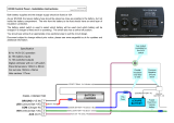
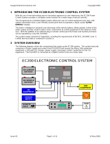
Diagrams of the 12V connectors / terminals located on the circuit board and the and 230V
connectors / terminals located on the rear housing are shown below for reference.
Sargent Electrical Services Ltd.
EC160 Power Supply – Installation Instructions
Issue 01 21/6/13
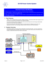
IMPORTANT
SAFETY REQUIREMENTS
This installation, or part of it, is protected by a
device which automatically switches off the
supply if an earth fault develops. Test each
time you hook-up by pressing the button
marked `T` or `Test`. The device should
switch off the supply and should then be
switched on to restore the supply. If the device
does not switch off the supply when the button
is pressed, seek expert advice.
This installation should be periodically
inspected and tested and a report on its
condition obtained, as prescribed in the IEE
Wiring Regulations BS7671 Requirements for
Electrical Installations.
Date of last inspection …………..…………………....
Recommended date of next inspection …....……
GND
LB
VB
Battery Inputs
GND
GND
GND
GND
PERM
LT
PUMP
AUX
EMC
SPLIT
FR IN
FR OUT
Circuit Outputs
L E N
MCB 1 Output
L E N
MCB 2 Output
L E N
MCB 3 Output Earth Bond

For your safety it is IMPORTANT that you follow these connections instructions each time
your Leisure Vehicle is connected to a mains supply. This section assumes that the system
is complete and that a Leisure battery has been installed.
Ensure suitability of the Mains Supply. Your Leisure Vehicle should only be connected to
an approved supply that meets the requirements of BS7671 or relevant harmonised
standards. In most cases the site warden will hold information regarding suitability of supply.
If using a generator you also need to comply with the requirements / instructions supplied
with the generator. Please note that some electronic generators may not be compatible with
your leisure system.
Switch the Power Supply Unit internal Battery Charger OFF. Locate the battery charger
power switch on the PSU and ensure the switch is in the off position (switch up) before
connection to the mains supply.
Connect the Hook-up Lead. Firstly connect the hook-up lead (orange cable with blue
connectors) to the Leisure Vehicle and then connect to the mains supply.
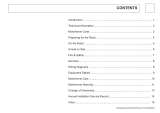
Check Residual Current Device operation. Locate the RCD within the PSU and ensure
the RCD is switched on (lever in up position). Press the ‘Test’ button and confirm that the
RCD turns off (lever in down position). Switch the RCD back to the on position (lever in up
position). If the test button failed to operate the RCD please check the mains supply.
Check Miniature Circuit Breakers. Locate the MCB’s within the PSU (adjacent to the
RCD) and ensure they are all in the on (up) position. If any MCB fails to ‘latch’ in the on
position seek expert help.
Turn the PSU ON. Locate the battery select switch (Vehicle / Leisure) and switch to the
leisure position to select the leisure battery. If the installation is in a motorhome or caravan
with the car attached, then the switch can be moved to the vehicle position to use the vehicle
battery if required. Now locate the battery charger switch and switch to the on position. The
battery charger will now start to charge the selected battery.
Check correct Polarity. Locate the ‘Reverse Polarity’ indicator on the PSU and ensure that
the indicator is NOT illuminated. If the indicator is illuminated then this could be caused by a
reversed supply, portable generator being used or faulty hook up cable. In this case please
seek expert advice.
Check operation of equipment. It is now safe to operate the 12V and 230V equipment.
Depending on how the system has been wired, the Lights / Aux switch with turn on / off the
lighting circuit (this switch is often used as the master lights switch) and the auxiliary circuit
(which is often used for 12V sockets, TV amplifier, heater and oven igniters etc). The pump
switch is used to turn on / off the water pump (and also in many cases the toilet flush pump).
Sargent Electrical Services Ltd.
EC160 Power Supply -Operating Instructions
Issue 01 21/6/13
Outline Specification
230V AC
16A input via pre wired 2M lead, RCD protected with reverse polarity indication
Build in 150W 13.8V fixed voltage battery charger with on / off switch
3 x 10A MCB outputs via quick fit connector blocks
12V DC
2 x 15A battery inputs via screw terminal block
5 x outputs via screw terminal block
-Pump output via Pump switch and 5A fuse
-Lights output via Lights/Aux switch and Lights 10A fuse
-Aux output via Lights/Aux switch and Aux 10A fuse
-Permanent output via 5A fuse
-Fridge output via 15A fuse
Built in split charge relay (configurable)
Built in EMC isolation relay (configurable)
Digital voltmeter with on / off switch
Dimensions
Front panel 300 x 150mm
Panel cut out 285 x 132mm
Depth 200mm
Notes
The EC160 150W power supply is also available with a stainless steel front.
The unit should only be cleaned with a dry or damp cloth, please do not use
abrasive or solvent cleaners. Document subject to change without prior notice,
please see www.sargenttld.co.uk for updates and additional information.
/