Page is loading ...

LEISURE BATTERY -VE
VEHICLE
BATTERY -VE
1
3
2
LEISURE
BATTERY
VEH (Vehicle Batt +)
LEIS (Leisure Batt +)
VEHICLE BATTERY +VE
BATTERY CONNECTOR
Double
insulation
over feed
to fuse
15A
Fuse
12V SOCKET (FUSE 3)
LIGHTS (FUSE 2)
PUMPS (FUSE 1)
Lights output
controlled by
the LIGHTS
switch
6
7
8
OUTPUT CONNECTOR
AUX (OUT)
LIGHTS (OUT)
PUMPS (OUT)
COM (Charger IN)
Pump output
controlled by
the PUMP
Switch
Aux output
controlled by
the AUX
switch
5
-VE INPUT (for Voltmeter only)
BATTERY
CHARGER
GROUND (-VE IN)
15A
LEISURE BATTERY +VE
15A
Common
Negative
Ground
block
Fused
Feed from
Vehicle
battery
LEIS
COM
VEH
PUMP
LIGHTS
AUX
GROUND
Circuit board at
the rear of the
control panel
15A
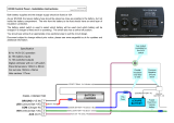
Both battery supplies and the charger supply should be fused at 15A.
As per EN1648, the leisure battery fuse should be placed as close as possible to the battery, but
not inside the battery compartment. The wire from the battery to the fuse should have an extra
layer of insulation / protection.
The battery select switch is used to select which battery will be used (and which battery will be
charged if a charger is fitted and it is operating). The switch also has a central off position.
You should use wiring of an appropriate cross sectional area to suit the circuit design.
Document subject to change without prior notice, please see www.sargenttld.co.uk for updates
and additional information.
Specification
9V to 14.5V DC operation
2x 15A battery inputs
3x 10A switched outputs
Digital voltmeter with on / off switch
Panel dimensions 193mm x 80mm
Cut out size 165mm x 65mm
Hole centres 180mm
Sargent Electrical Services Ltd.
EC30 Control Panel -Installation Instructions
Issue 01 21/6/13
/