Page is loading ...

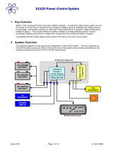
AUXILIARY / AWNING LIGHT (FUSE 6)
Relay turns ON when
engine running
Connection to
alternator / charging
light wire
Connection / splice between
vehicle battery and your wiring
harness
EARTH
EARTH
3
6
2
5
1
4
13
9
10
11
1
2
5
6
7
4
8
14
VEHICLE
BATTERY +VE
VEHICLE BATTERY EARTH
FRIDGE
VEHICLE BATTERY (FUSE 2)
LEISURE BATTERY (FUSE 1)
LEISURE BATTERY (FUSE 1)
VEHICLE BATTERY (FUSE 2)
RADIO (FUSE 3)
12V SOCKET (FUSE 9)
12V SOCKET (FUSE 9)
IGNITIONS (FUSE 11)
FRONT LIGHTS (FUSE 7)
FRONT LIGHTS (FUSE 7)
HEATER FANS (FUSE 10)
REAR LIGHTS (FUSE 8)
REAR LIGHTS (FUSE 8)
EXTRACTOR FANS (FUSE 10)
TOILET PUMP (FUSE 12)
INTERNAL WATER PUMP (FUSE 4)
20A
FUSE
LEISURE
BATTERY
POWER CONNOUTPUT CONNECTOR
INPUT SUPPLY
FOR FRIDGE
Common earth point, usually a
splice or ‘commoning’ terminal
added to your wiring harness
If the Fridge requires
a permanent supply
for the ‘electronics’
then this can be taken
from terminal 13
Double
insulation
over feed
to fuse
FRIDGE RELAY
VEHICLE
BATTERY
20A
20A
30 to 40A Rated
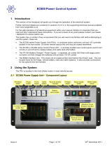
Basic Motorhome 12V Connections
Double
insulation
over feed
to fuses
10
6
5
4
8
7
9
3
2
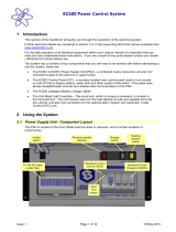
SIGNAL CONNECTOR
1
WASTE
100%
WASTE
50%
FRESH
TANK
100%
75%
50%
25%
15
3
12
EXTERNAL WATER PUMP (FUSE 5)
NOT USED
Connector Notes: Terminal
13 permanent supply.
Terminals 14 & 15 controlled
by the control panel PUMP
button. Terminal 3 controlled
by the control panel AUX.
Remaining terminals are
switched on / off by the
control panel POWER button.
Where 2 terminal pins are provided please use both terminals to share the input / output load
EC328 Basic Connection Diagram Issue 1 29/01/14
RADIO
NOT USED

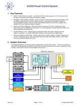
E
E
N
L
1
2
3
4
5
6
7
8
9
FEED TO FRIDGE
FROM 6A MCB 3
FEED TO SOCKETS
FROM 10A MCB 1
FEED TO HEATER
FROM 10A MCB 2
1
2
3
4
5
6
7
8
9
FEED TO BOILER
FROM 6A MCB 3
FEED TO SOCKETS
FROM 10A MCB 1
FEED TO EXTRA SOCKETS
FROM 10A MCB 2
230V INPUT230V OUTPUT 1230V OUTPUT 2
4
m
m
F
L
E
X
HOOK-UP
INPUT
SOCKET
EARTH BOND CABLE, CONNECT TO
CHASSIS AND TO GAS PIPE IF FITTED
Use one continuous
piece of cable, do
not cut at terminal
230v output connectors 1 & 2 are wired identical, you can use either connector or both depending on you wiring requirements
1.5mm FLEX
15.mm FLEX
1.5mm FLEX
1.5mm FLEX
15.mm FLEX
1.5mm FLEX
2.5mm FLEX
EC325 / EC328 Basic Mains Wiring Issue 2 29/01/14
CHASSIS
GAS PIPE
/