Page is loading ...

EC500 Controller
Operation Handbook
Issue A1
Issue Date: March 2019

EC500 Controller Handbook
Copyright © 2019 Eaton Corporation. All Rights Reserved.
Issue A March 2019 Page 2 of 107
The product discussed in this literature is subject to terms and conditions outlined in Eaton selling policies. The sole source
governing the rights and remedies of any purchaser of this equipment is the relevant Eaton selling policy.
No warranties, express or implied, including warranties of fitness for a particular purpose or merchantability, or warranties arising
from course of dealing or usage of trade, are made regarding the information, recommendations and descriptions contained
herein.
In no event will Eaton be responsible to the purchaser or user in contract, in tort (including negligence), strict liability or otherwise
for any special, indirect, incidental or consequential damage or loss whatsoever, including but not limited to damage or loss of
use of equipment, plant or power system, cost of capital, loss of power, additional expenses in the use of existing power facilities,
or claims against the purchaser or user by its customers resulting from the use of the information, recommendations and
descriptions contained herein.
The information contained in this literature is subject to change without notice.
Subject to the right to use its equipment, Eaton Corporation does not convey any right, title or interest in its intellectual property,
including, without limitation, its patents, copyrights and know-how.
No part of this literature may be reproduced or transmitted in any form, by any means or for any purpose other than the
Purchaser’s personal use, without the express written permission of Eaton Corporation.
Eaton
®
, Matrix, Powerware
®
, Intergy
TM
, CellSure
TM
, SiteSure
TM
, PowerManagerII
TM
and DCTools
TM
are trade names, trademarks,
and/or service marks of Eaton Corporation or its subsidiaries and affiliates. Unless otherwise noted, brands, product names,
trademarks or registered trademarks are the property of their respective holders.
Copyright © 2007-2019 Eaton Corporation. All Rights Reserved.

EC500 Controller Handbook Contents
Copyright © 2019 Eaton Corporation. All Rights Reserved.
Issue A March 2019 Page 3 of 107
CONTENTS
About This Guide.............................................................................................................................. 6
Scope ................................................................................................................................................... 6
Audience ............................................................................................................................................. 6
Reporting Problem With This Guide ................................................................................................... 6
For Further Information and Technical Assistance ............................................................................. 6
Third Party Software ........................................................................................................................... 6
General Description ......................................................................................................................... 7
Overview ............................................................................................................................................. 7
EC500 Controller ................................................................................................................................. 7
DC Interface and IO Board .................................................................................................................. 8
IOB-6V3C ......................................................................................................................................... 8
Potential Free Input / Output Board ................................................................................................... 9
Connections ...................................................................................................................................... 10
Board Options ................................................................................................................................... 11
EC500 Operation ............................................................................................................................ 12
Overview ........................................................................................................................................... 12
Starting the EC500 ............................................................................................................................ 12
Home Screen ................................................................................................................................. 13
EC500 Operation Using Keypad and Screen ..................................................................................... 13
Navigation Keys ............................................................................................................................. 13
Main Menu Navigation ................................................................................................................. 14
Changing a Configuration Setting using the Keypad ..................................................................... 14
Keypad Access Security ................................................................................................................. 14
Display Settings ............................................................................................................................. 15
Display Time-out ........................................................................................................................... 15
Alarm Indicators ............................................................................................................................ 15
EC500 Operation Using a PC/Laptop ................................................................................................ 16
EC500 Identity Information ............................................................................................................... 17
Identity Information ...................................................................................................................... 17
EC500 Internal Clock ......................................................................................................................... 18
Time Synchronization .................................................................................................................... 19
Language Options ............................................................................................................................. 19
Language Selection ....................................................................................................................... 20
EC500 Firmware Upgrade ................................................................................................................. 20
Software Downgrade .................................................................................................................... 20
Configuration File .............................................................................................................................. 21
System Operation .......................................................................................................................... 22
Overview ........................................................................................................................................... 22
Battery and Voltage Control ............................................................................................................. 22
VRLA Battery Charge Profile ......................................................................................................... 23
Battery Current Limit .................................................................................................................... 24
Multiple Battery Banks.................................................................................................................. 24
Battery Temperature Compensation ............................................................................................ 26
Equalize ......................................................................................................................................... 27
Battery Test ................................................................................................................................... 29
Battery Reverse Detection ............................................................................................................ 30
Manual Charge Mode ................................................................................................................... 30
Solar Charger Power Share ........................................................................................................... 31

EC500 Controller Handbook Contents
Copyright © 2019 Eaton Corporation. All Rights Reserved.
Issue A March 2019 Page 4 of 107
Rectifiers ........................................................................................................................................... 34
Rectifier Registration .................................................................................................................... 36
Identify a Rectifier ......................................................................................................................... 37
Force Share Reset ......................................................................................................................... 37
Rectifier Sleep Mode ..................................................................................................................... 38
Economy Mode ............................................................................................................................. 38
Rectifier Alarms ............................................................................................................................. 41
Low Voltage Disconnect (LVD) .......................................................................................................... 42
Bus Monitoring ............................................................................................................................. 42
Battery LVD ................................................................................................................................... 43
Load LVD ....................................................................................................................................... 44
Typical LVD Arrangements ............................................................................................................ 44
LVD Operation ............................................................................................................................... 44
DCDB Alarms ................................................................................................................................. 45
Alarms ............................................................................................................................................... 45
Type of Alarms .............................................................................................................................. 45
Active Alarm Indications ............................................................................................................... 46
Alarm Change Indication ............................................................................................................... 47
Alarm Grouping ............................................................................................................................. 47
System Alarms ............................................................................................................................... 47
Potential Free Inputs / DI Alarms .................................................................................................. 48
Analog Alarms ............................................................................................................................... 49
Smart Alarms ................................................................................................................................. 51
Potential Free Outputs .................................................................................................................. 52
Common Alarm Parameters ......................................................................................................... 53
Generator Control ............................................................................................................................. 53
Input / Output (I/O) .......................................................................................................................... 55
Identify an I/O Board .................................................................................................................... 55
Analog System Values ................................................................................................................... 55
Analog Inputs ................................................................................................................................ 56
System States ................................................................................................................................ 58
Digital Inputs ................................................................................................................................. 58
Digital Outputs .............................................................................................................................. 59
Energy Metering ............................................................................................................................... 60
Information ................................................................................................................................... 60
Configuration ................................................................................................................................ 61
Data Logging...................................................................................................................................... 62
Event Log ....................................................................................................................................... 62
Data Log ........................................................................................................................................ 63
Energy Log ..................................................................................................................................... 63
Run Hours Log ............................................................................................................................... 64
Status Logs .................................................................................................................................... 64
Change Logs .................................................................................................................................. 65
Performance logs .......................................................................................................................... 65
System Configuration ..................................................................................................................... 67
Overview ........................................................................................................................................... 67
System Info ....................................................................................................................................... 67
Battery Configuration ....................................................................................................................... 68
Battery Mid-Point Configuration ...................................................................................................... 70
Load Configuration ............................................................................................................................ 72
Current Sensing ................................................................................................................................. 72

EC500 Controller Handbook Contents
Copyright © 2019 Eaton Corporation. All Rights Reserved.
Issue A March 2019 Page 5 of 107
Cabinet Configuration ....................................................................................................................... 73
Hardware Channel Mapping ............................................................................................................. 74
Channel Naming Convention ........................................................................................................ 74
Battery Channel Mappings ............................................................................................................ 76
Load Channel Mappings ................................................................................................................ 77
Cabinet Channel Mappings ........................................................................................................... 78
Communications ............................................................................................................................ 79
Communications Options ................................................................................................................. 79
Ethernet Communications ................................................................................................................ 79
Ethernet Communication Set-up .................................................................................................. 79
Communication via Web Browser ................................................................................................ 82
Communication via a Network Management System using SNMP .............................................. 83
SNMP Access Configurations ........................................................................................................ 83
SNMP trap Configurations ............................................................................................................ 85
Communication via Email ............................................................................................................. 88
Modbus Communications ................................................................................................................. 89
Communications Security ................................................................................................................. 89
Web Access Security ..................................................................................................................... 89
Web User Setup ............................................................................................................................ 90
Specifications ................................................................................................................................. 92
EC500 Controller ............................................................................................................................... 92
Interfaces ...................................................................................................................................... 92
User Input and Display .................................................................................................................. 92
Power, Mechanical & Environmental ........................................................................................... 93
DC Interface Board ............................................................................................................................ 94
Potential Free Input / Output Board ................................................................................................. 95
System Maximum Capacities (Software) .......................................................................................... 95
Alarm Descriptions ......................................................................................................................... 97
Connector Pin-outs ...................................................................................................................... 100
System Controller Connector Pin-outs ........................................................................................... 100
DCIF Connector Pin-outs ................................................................................................................. 102
DCIO (IOB-6V3C) Connector Pin-outs ............................................................................................. 103
Support......................................................................................................................................... 107

EC500 Controller Handbook About this guide
Copyright © 2019 Eaton Corporation. All Rights Reserved.
Issue A March 2019 Page 6 of 107
ABOUT THIS GUIDE
SCOPE
This guide covers operation of the EC500 Controller.
See EC500 Identity Information on page 17 to determine the version of the embedded
software.
AUDIENCE
This guide is intended for use by:
• Installers competent in:
• installing and commissioning dc power systems
• safe working practices for ac and dc powered equipment
• the relevant local electrical safety regulations and wiring standards
• Operators and maintenance staff competent in:
• operation of dc power systems
• safe working practices for ac and dc powered equipment
REPORTING PROBLEM WITH THIS GUIDE
Please use this email address to report any problem you find in this guide:
FOR FURTHER INFORMATION AND TECHNICAL ASSISTANCE
For further information and technical assistance contact dcinfo@Eaton.com
THIRD PARTY SOFTWARE
This product includes an open source SSL library “mbed TLS” licensed by ARM Limited. Source code of
“mbed TLS” can be downloaded from https://tls.mbed.org/.

EC500 Controller Handbook General Description
Copyright © 2019 Eaton Corporation. All Rights Reserved.
Issue A March 2019 Page 7 of 107
GENERAL DESCRIPTION
OVERVIEW
Topic
Page
EC500 Controller
7
DC Interface and IO Board
8
Connections
10
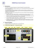
EC500 CONTROLLER
The EC500 Controller is an advanced control and monitoring solution which provides a full suite of
communications options, including built-in Ethernet interface, Web server, Modbus, and SNMP agents.
Alarm notifications may be by Email, SNMP traps, SMS text messaging or relay contact closures. Local
notifications are given on Display, Buzzer and LEDs.
EC500 Front View
ITEM
NOMENCLATURE
1
Power LED/normal conditions
2
Major Alarm
3
Info Alarm
4
Display Screen
5
Left Key/ Scroll/Back
6
Right Key/Scroll
7
Up Key/Scroll/Parameter Value Change/ Latch reset
8
Down Key/Scroll/Parameter Value Change
7
6
8
9
5
11
10
2
3
1
4

EC500 Controller Handbook General Description
Copyright © 2019 Eaton Corporation. All Rights Reserved.
Issue A March 2019 Page 8 of 107
ITEM
NOMENCLATURE
9
Enter Key
10
Ethernet Port
11
USB Port
EC500 Rear View
ITEM
NOMENCLATURE
1
CAN Port 1 + Power
2
RS 485 Port (Lower) + Power
3
CAN Port 2 (Optional) + Power
4
RS 485 Port (Upper, Optional) + Power
5
RS232 Port, GSM Modem
The EC500 is supplied pre-configured with either a default configuration file, or with one factory customized
for a particular application. Some configuration file changes can be made with the keypad, or all settings can
be changed via a PC connected to the EC500 through a network. For essential configurations see System
Configurations on page 67.
For connector pin-outs see details on page100. See Troubleshooting on page Error! Bookmark not defined. for
details of EC500 alarm LEDs.
DC INTERFACE AND IO BOARD
The DC Interface & IO provides the Analogue interfaces, I/O interfaces and connections for system bus.
The DC Interface board includes a range of sense inputs for dc power system control and monitoring. It also
allows real time data collection from building services and other external devices, relay outputs for alarm
signals or control of external devices and drives for DC Contactors.
DCIO board provide Shunt based current sensing. All voltage and current measurements are in reference to
Bus Common (-48V DC).
IOB-6V3C
• Sensors: Current – 3, Bus Voltage – 1, Battery/Mid-point – 5, Temperature – 2
• Input/Outputs: Optically Isolated Inputs – 8, Relays – 8, LVD Contactor Relays – 3
1
2
3
4
5

EC500 Controller Handbook General Description
Copyright © 2019 Eaton Corporation. All Rights Reserved.
Issue A March 2019 Page 9 of 107
This board provides 8 on board relays for alarm or other control functions.
The IOB-6V3C board provides 3 on board LVD Contactor relays.
For input and output specifications see details on page 94. For connector pin-outs see details
on page 102.
POTENTIAL FREE INPUT / OUTPUT BOARD
A variant of DCIO provides only 8 PFC Inputs and 8 PFC Outputs. This board can be used where additional
digital monitoring inputs and additional potential free contacts are required, but analogue inputs are not
required. The board communicates with the controller on the system CAN bus. For connector pin outs see
DCIF Connector Pin-outs on Page 102.
This board provides following interfaces:
• Input / Outputs: Optically isolated inputs – 8, Relay (NO / NC) – 8

EC500 Controller Handbook General Description
Copyright © 2019 Eaton Corporation. All Rights Reserved.
Issue A March 2019 Page 10 of 107
CONNECTIONS
The following diagram shows a system architecture using EC500 and its peripherals.
The following wiring diagram shows the connections between the EC500, the DC Interface board, the other dc
power system components and external devices for a generic power plant. Please refer to your system wiring
diagram for any system specific changes.
For connector pin-outs see details on page 100. For input and output specifications see details
on page 100.

EC500 Controller Handbook General Description
Copyright © 2019 Eaton Corporation. All Rights Reserved.
Issue A March 2019 Page 11 of 107
BOARD OPTIONS
The EC500 system includes a number of options for controller and input / output boards. Contact Eaton for
any new or currently available options.
Unit
Unit Features
Remarks
EC500-00
Controller
EC500 Controller with 10/100Mbps
Ethernet, USB, 1x CAN, 1xRS485 and
1xRS232
EC500-01
Controller
EC500 Controller with 10/100Mbps
Ethernet, USB, 2x CAN, 2xRS485,
1xRS232 and 4GB SD card
To special order.
Contact Eaton.
IOB-6V3C
DC Interface unit
Cased, 6Voltage, 3 Current, 8 PFC inputs,
8 PFC outputs, 3 LVD, Bus Powered
Shunt based current
sensors
IOB-PFCIO-8
DC Interface Unit
Cased, 8 PFC inputs, 8 PFC outputs, Bus
Powered
To special order.
Contact Eaton.

EC500 Controller Handbook EC500 Operation
Copyright © 2019 Eaton Corporation. All Rights Reserved.
Issue A March 2019 Page 12 of 107
EC500 OPERATION
OVERVIEW
Topic
Page
Starting the EC500
12
EC500 Operation Using Keypad and Screen
13
EC500 Operation Using a PC/Laptop
16
EC500 Identity Information
17
EC500 Internal Clock
18
Language Options
19
EC500 Firmware Upgrade
20
STARTING THE EC500
When dc power is applied to the EC500 (via the connector CAN-1 / CAN-2 / RS485-L / RS485-U on rear panel)
the controller boots up and start-up sequence begins.
Start-up Screen
At power up, Boot loader
loads any new firmware and
then jumps to application.
Controller initializes
hardware, loads system
settings and starts operation.
Home Screen
Display system values, alarm
status, latest alarm and date /
time. Colour of particular
block shows alarm status of
that block.
Main Menu
Option selection displays
Main Menu. See
navigation on page 13. If Logon is
required see Keypad Access
Security on page 14.
CAN-2 and RS485-U are not part of standard offering and must be purchased as an option
(EC500-01)

EC500 Controller Handbook EC500 Operation
Copyright © 2019 Eaton Corporation. All Rights Reserved.
Issue A March 2019 Page 13 of 107
HOME SCREEN
The Home screen displays important system parameter values and system block status. Block nomenclature
and colour relations are as given below.
ITEM
NOMENCLATURE
ITEM
NOMENCLATURE
AC Input
Alarms
Rectifier
Selection Indicator
Solar Input
System Status
Battery Bank
Menu
Current Flow
Load
Home Screen or default screen parameters are read only and are used to show important system parameters
such as Date and Time, Last event, AC phase (RYB) voltage, Rectifier Current, Battery current & voltage, Load
current and bus voltage.
EC500 OPERATION USING KEYPAD AND SCREEN
NAVIGATION KEYS
EC500 provides a Joystick for navigation. For Navigation towards Right push the joystick Rightwards, for Left
push leftwards and similarly, for Up and Down directions. To select an option or Enter, press the joystick
towards the centre.
User can navigate through all enabled screen using the joystick. Joystick functions change according to context.
Important functions are given below.
ITEM
Key Operation / Key Direction
To Select an Option (Yes / No)
Select using Left / Right and then Enter
To select a sub menu
Select using Up / Down and then Enter. On Main menu use
Left / Right and then enter
Previous Menu Item
Left
Scroll through sub menus
Up / Down

EC500 Controller Handbook EC500 Operation
Copyright © 2019 Eaton Corporation. All Rights Reserved.
Issue A March 2019 Page 14 of 107
Edit a parameter
Up / Down to change value, Enter to select current displayed value
Increase / decrease number of characters
When at last location of string, Right press will add one character
location. When at last display location, Left press will reduce string
length.
Fast Scroll
push and hold the joystick in the respective direction
Buzzer mute
When at Home screen, move joystick in any direction to
turn off Buzzer (if sounding). On new event, Buzzer will
again start to beep, unless Buzzer is permanently disabled
under System settings.
MAIN MENU NAVIGATION
To navigate to Main Menu, from Home screen navigate to the Main Menu icon and press enter.
The following menu items will appear: System Status, Logs, Settings, System Configuration, Maintenance and
Accessories. These can be navigated using left and right navigation keys. To select a particular menu use the
Enter Key. Sub menu items under the selected menu will appear.
CHANGING A CONFIGURATION SETTING USING THE KEYPAD
To change value or configuration of a parameter, the user must have edit access rights and must login. To
change the value of a parameter, navigate to the parameter and press Enter. If not logged in already, then a
login window will popup else a popup window to change parameter will appear. Use Up and Down key to
change value (for changing values rapidly, hold the key in up (increment) or down (decrement) direction. Once
desired value has been set on display, press Enter to save. Valid limits of the parameter are also displayed in
the Edit window. Once the selected value is saved, a “SAVED” message will be displayed. Left press to exit Edit
window.
KEYPAD ACCESS SECURITY
To get Keypad access for changing any setting or configuration, user must first login with the access pin. Login
screen is presented when a user selects a parameter for edit.
➢ To Login
• Select the system parameter that is to be modified.
• If user is already logged in, then the settings can be directly changed, if he/she has required
access rights else a login window will popup.
• Enter the access PIN.
• To enter PIN, move joystick up / down to scroll through numbers 0 -9. To enter next digit
move joystick to right and then up / down to select next digit.
• Selected digit will be displayed for a short duration and then will be hidden using a * symbol.
• Once all required digits are selected, push joystick to Enter.
• Cursor moves to Login button, again push joystick to Enter.
• If PIN is incorrect, user is taken back to Login window.
User will be auto logged out 5 minutes after last parameter edit.

EC500 Controller Handbook EC500 Operation
Copyright © 2019 Eaton Corporation. All Rights Reserved.
Issue A March 2019 Page 15 of 107
For example, if a user wants to change Battery Capacity then go to Home Main Menu Settings
Battery Settings General Settings Battery Capacity and press Enter. If User is not already logged in, a
pop-up window for PIN entry will appear.
DISPLAY SETTINGS
In Display Settings, a user can set brightness level.
➢ To set Brightness level
• Home Main Menu Settings System Settings Brightness.
• Change level (10% – 100%) using up and down keys.
• Enter to save.
Adjust display intensity according to ambient light, else you may not be able to see the
display values
DISPLAY TIME-OUT
If there is no keypad activity for 60 seconds, the display will jump back to the Home screen.
When the display is at Home screen and there is no user activity for 60 seconds, the display intensity
automatically reduces to half (minimum 10%). If there is no activity for further 180 seconds then the intensity
is reduced to 10%. Display intensity will increase automatically to set value when any key is pressed or any
event occurs.
ALARM INDICATORS
Enter
Enter PIN to
Login
Press Login Button
Login Successful and
now the value can
be configured. Press
Enter to Configure.
Change the Value
using up/down
navigation and Press
Enter to save.
Enter
Enter
Login
Window
Enter

EC500 Controller Handbook EC500 Operation
Copyright © 2019 Eaton Corporation. All Rights Reserved.
Issue A March 2019 Page 16 of 107
Active alarms are displayed at the bottom left side of the Display. Alarms are categorised as Critical, Major and
Minor. If a Critical or Major Alarm occurs than Status LEDs will glow in Red colour and if a Minor alarm occurs
than Status LEDs glow in Yellow colour.
Visual Indicators
Audio Indicators
Whenever any alarm is present, the Buzzer will beep every 2 seconds
➢ To stop the audible indicator
On Home screen move the joystick in any direction (up / down / left / right)
The audible indicator will restart at the next active alarm or alert message.
➢ To enable / disable the audible alarm indicator
Either:
• Use the keypad to go to: Home Main Menu Settings System Settings Buzzer
• Set Buzzer status to Disable and save.
Or:
• On Web page go to: Home Settings System Settings Buzzer Status
• Set Buzzer status to Disable and save.
EC500 OPERATION USING A PC/LAPTOP
EC500 can be operated using a PC/Laptop through the Ethernet port.
Connect to the EC500 either directly or over a network. Before connecting, ensure you know the IP address,
user id and password to login to EC500. Please obtain your User name and password from your network
administrator.
To see the IP address of EC500 on display go to
For IPv4:
Home Main Menu Settings Communication Settings Ethernet IPv4 IP Address
For IPv6 Link Local / Network Address:
Home Main Menu Settings Communication Settings Ethernet IPv6 Link Local / IPv6 Address
Refer section Ethernet Communication Set-up on page 79 for setting static IP address or
enabling DHCP client.
Power on LED (green)
Critical/Major Alarm LED (Red)
Minor Alarm LED (yellow)

EC500 Controller Handbook EC500 Operation
Copyright © 2019 Eaton Corporation. All Rights Reserved.
Issue A March 2019 Page 17 of 107
Refer section Communication via Web Browser on page 82 for establishing communication
using a Web browser.
Open any standard Web Browser, enter IP address of the controller and press enter. Browser will connect to
the controller and a Login page will be presented. Enter your credentials and you will be presented with EC500
data.
By default, the EC500 Controller comes enabled for HTTPS communication. You will need to add "https://"
before the IP Address.
Recommended web browsers: Microsoft Internet Explorer 10 or later, Mozilla Firefox 3.0 or
later, Chrome V63 or later.
It is recommended to keep web communication mode to HTTPS to ensure a secure network.
EC500 IDENTITY INFORMATION
The following identity information is available for the EC500:
IDENTITY INFORMATION
Parameter
Description
Where to find:
Model No.
Indicates Model number of the controller, EC500.
Display:
Home > Menu > System
Status > System Info
Web:
Home > System Status >
System Info
Controller Serial
Number
EC500 serial number. Factory set.
Srl. No.: xxxxxxxxxxxxxxx
Boot Loader
Version
Indicates boot loader version vv.xx format. Factory
loaded.
Firmware Version
Indicates currently loaded firmware version in
CC.vv.xx format, where “CC” is hardware group
category of controller. For EC500 category is 34.
Configuration File
Version
Indicates currently loaded Configuration file version
in vv.xx format. If no configuration file is loaded,
controller can run with default configuration and this
version is shown as 00.00
MAC ID
Unique MAC ID of the Ethernet interface. Factory
loaded.
Display:
Home > Menu > Settings >
Communication Settings >
Ethernet
Web:
Home > Settings >
Communication Settings >
Ethernet
Following additional information can be stored to help system and site location.
Parameter
Description
Where to find:
Site Name
User can store a 12 character Site Name where the
system is installed.
Display:

EC500 Controller Handbook EC500 Operation
Copyright © 2019 Eaton Corporation. All Rights Reserved.
Issue A March 2019 Page 18 of 107
Parameter
Description
Where to find:
Site ID
User can store Site ID where the system is installed.
Site ID can be allocated by monitoring servers for
network wide management. Site ID can be an
alphanumeric string with length 12.
Home > Menu > Settings >
System Settings
Web:
Home > Settings > System
Settings
System Part
Number
User can store System part number in which this
controller has been used. This is to help inventory
management.
System Serial
Number
User can store Serial number of the system in which
this controller has been used. This is to help
inventory management.
EC500 INTERNAL CLOCK
The EC500 has a battery-backed clock for time stamping of log entries and Control Processes.
The time and date are factory set. They can also be set manually using a web browser or can be synchronized
to an SNTP reference time server.
➢ To view the EC500 time
Either:
• Use the keypad on controller to go to: Home Screen.
Time is displayed on lower right corner in DD/MM/YY HH:MM:SS format.
Or:
• In Web go to: Home Page
Time is displayed on lower right corner in DD/MM/YY HH:MM:SS format.
➢ To set the time on Web
• Connect to the EC500 via a web browser (See Ethernet Communications on page 79).
• Go to Home Settings System Settings.
• Click on Edit button to enable editing
• Click Date and Time field to select the text.
• Select the time or date text to be changed and type the correct time/date.
• Click Save button on Web page.
➢ To set the time from Display
• On EC500 display, go to Home Main Menu Settings System Settings Date and
Time.
• Enter on Date or Time field, if not logged in then login first and change the date or time.
• Enter to save.

EC500 Controller Handbook EC500 Operation
Copyright © 2019 Eaton Corporation. All Rights Reserved.
Issue A March 2019 Page 19 of 107
TIME SYNCHRONIZATION
If required, the EC500 time can be synchronized to a reference time server using SNTP protocol (EC500 must
have access to the server).
➢ To synchronize the EC500 time using SNTP
• Connect to the EC500 via a web browser (See Ethernet Communications on page 79).
• Go to Home Settings System Settings.
• Click on Edit button to enable editing
• Click Date and Time field to select the text.
• Select Auto under Synchronisation field and click Save button. Web page will refresh and
display NTP server settings.
• Set the following parameters:
Server IP Type
IP Type IPv4 or IPv6.
Server IP Address
IP address of primary SNTP server.
UDP Port
Assigned by the time server
administrator.
Poll Interval
The time between synchronizations.
• Click Save button again on Web page.
For more information on SNTP, including a list of public SNTP servers, visit www.ntp.org
http://www.ntp.org.
Ensure that your network has an internal SNTP server or allows access to an external server.
It may be necessary to configure access through your network's firewall.
LANGUAGE OPTIONS
The EC500 Controller language default is English and is inbuilt. Text on the LCD can be shown in other
languages by loading the appropriate Translation File (EC500-xx-Vyyy.lng) into the EC500. Only Menu item
translation is supported. User entered strings and alarm strings are shown in English language only. Only one
language file can be loaded in addition to English.
The controller validates the language file for any corruption at power on / reboot. In case of any corruption the
language file is discarded and controller returns to English language, if another language was selected.
The existing language file will be normally supported in case of a firmware upgrade. In case translation of new
messages is not available, particular messages will be shown in English. In rare instances a firmware upgrade
may require a fresh language file compatible with this firmware.
Contact Eaton for available Translation Files. Current Firmware version does not support language translation
on Web pages.
➢ To add a new EC500 display language:
• Obtain the appropriate Translation File (EC500-xx-Vyyy.lng) from Eaton.
• Save the file on Laptop / PC.
• Connect to the EC500 via an Ethernet connection. See Communications Options on page 79.
• Open a web browser and browse to the EC500 IP address.

EC500 Controller Handbook EC500 Operation
Copyright © 2019 Eaton Corporation. All Rights Reserved.
Issue A March 2019 Page 20 of 107
• Go to System Config. File Management. Select Language Download.
• Click on Choose File and select the Translation File (EC500-xx-Vyyy.lng).
• Click on Upload and follow the prompts to add the language.
LANGUAGE SELECTION
EC500 can hold one language file (in addition to inbuilt support for English) and it can be selected from the
Display or Web page.
➢ To select a new language for the EC500 display
Either:
• On the EC500 keypad go to: Home Main Menu Settings System Settings Set
Language
• Select Language (English or second loaded language).
• Go back to Home screen. Controller will start showing messages in selected language.
Or:
• Connect to the EC500 via a web browser (See Ethernet Communications on page 79).
• Go to Settings System Settings.
• Click on Edit button to enable editing
• Click Set Language field to select the Language from drop down.
• Click Save button. EC500 language will change to selected language.
EC500 FIRMWARE UPGRADE
If required, the embedded software (firmware) in the EC500 can be upgraded from a PC/Laptop via a web
browser.
➢ To use a web browser for a Firmware Upgrade
• Obtain the appropriate Firmware File (EC500_nnn_GG.VV.RR.frm) from Eaton.
• Connect to the EC500 via a web browser (For details see Ethernet Communications on page
79).
• Go to System Config. File Management. Select Firmware Upgrade.
• Click on Choose File and select the firmware File (EC500_nnn_GG.VV.RR.bin).
• Click on Upload and follow the prompts.
• Web page & display will show progress.
• Once full file has been uploaded successfully, EC500 will automatically reboot within 5
Seconds. User will need to login again.
Some configuration settings may be lost when the firmware in the EC500 is upgraded. Refer to the
new firmware Product Release Notes for details of specific configuration settings that may be affected. Check
the configuration after upgrading. Backup any changes to the configuration.
SOFTWARE DOWNGRADE
/