Page is loading ...

Sargent Electrical Services Ltd. Copyright 2003
Issue 1 Page 1 of 4 12 January 2005
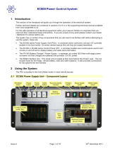
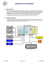
1 ELECTRICAL SYSTEM USING PSU 2005
1.1 INTRODUCTION
For the safe operation of all electrical equipment within your Caravan / Motorhome / Trailer Tent /
Folding Camper it is important that you read and fully understand these instructions. If you are unsure
of any point please contact your dealer / distributor for advice before use.
Your Caravan / Motorhome / Trailer Tent / Folding Camper has been fitted with an electrical system
from Sargent Electrical Services Ltd. and incorporates the new PSU2005 power supply. This unit
provides protection for the 240v (mains) and 12v equipment, supplies 12v power and charges the
internal leisure battery. The electrical system complies with EN 1648-1 & -2 and BS7671.
1.2 MAINS CONNECTION
For your safety it is IMPORTANT that you follow these connections instructions each time your
Caravan / Motorhome / Trailer Tent / Folding Camper is connected to a mains supply.
A) Ensure suitability of the Mains Supply. Your Caravan / Motorhome / Trailer Tent / Folding
Camper should only be connected to an approved supply that meets the requirements of BS7671.
In most cases the site warden will hold information regarding suitability of supply. If using a
generator you also need to comply with the requirements / instructions supplied with the generator.
B) Switch the PSU2005 unit OFF. Locate the red power switch on the PSU2005 and ensure the
switch is in the OFF (0) position before connection to the mains supply.
C) Connect the Hook-up Lead. Firstly connect the supplied hook-up lead (orange cable with blue
connectors) to the Caravan / Motorhome / Trailer Tent / Folding Camper and then connect to the
mains supply.
D) Check Residual Current Device operation. Locate the RCD within the PSU2005 and ensure the
RCD is switched on (lever in up position). Press the ‘TEST’ button and confirm that the RCD is
turned off (lever in down position). Switch the RCD back to the on position (lever in up position). If
the test button failed to operate the RCD see section 1.4.
E) Check Miniature Circuit Breakers. Locate the MCB’s within the PSU2005 (adjacent to the RCD)
and ensure they are all in the ON (up) position.
F) Turn the PSU2005 ON. Locate the red power switch on the PSU2005 and turn to the ON (I)
position. The switch will illuminate when turned on.
G) Check correct Polarity. Locate the ‘Reverse Polarity’ indicator on the PSU2005 and ensure that
the indicator is NOT illuminated. If the indicator is illuminated see section 1.4. Note that the
reverse polarity indicator only works when the red power switch is in the ON position. Also,
reverse polarity indicator may momentarily flicker as the red power switch is turned on / off, this is
normal and does not indicate a fault.
H) Check operation of equipment. It is now safe to check the operation of the 12v and 240v
equipment.
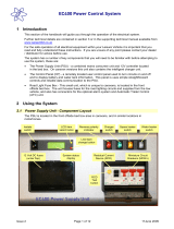
PSU2005 Layout PSU2005 Specification
Mains Input 230 Volts AC +/- 10%
Frequency 50 Hz
Output Voltage 13.5 Volts nominal
Output Current 12 Amps nominal
(150 Watts)

Sargent Electrical Services Ltd. Copyright 2003
Issue 1 Page 2 of 4 12 January 2005
1.3 BATTERY
A) Type / Selection
For optimum performance and safety it is essential that only a proprietary brand LEISURE battery is
used with a typical capacity of 75 to 120 Ah. A normal car battery is NOT suitable.
It is recommended that the leisure battery is always ‘in circuit’ when the system is in use.
The battery feed is fitted with an inline fuse between the battery and the electrical harness, which is
usually located immediately outside the battery compartment. The maximum rating of this fuse is 20A.
B) Installation & Removal
Always disconnect the 240v mains supply and turn the PSU2005 charger switch to the OFF (0)
position before removing or installing the battery.
When connecting the battery, ensure that the correct polarity is observed (black is negative [-] and red
is positive [+]) and that the terminals are securely fastened. Crocodile clips must not be used.
WARNING
Explosive gases may be present at the battery. Take care to prevent flames and sparks in the vicinity
of the battery and do not smoke.
C) Servicing
Under normal circumstances it should not be necessary to remove the battery other than for routine
inspection of the terminals and “topping up” of the battery fluid. Please see instructions supplied with
the battery.
Note: Do not over-discharge the battery. One of the most common causes of battery failure is when
the battery is discharged below the recommended level of approximately 10.5v. Discharging a battery
below this figure can cause permanent damage to one or more of the cells within the battery.
1.4 FAULT TABLE
Fault Possible Cause Proposed Fix
Connecting lead between the site and
Caravan / Motorhome / Trailer Tent /
Folding Camper not connected
Check and connect lead as per 1.2.C
Check also input connector at the base
of the PSU2005
RCD switched off Reset RCD as per 1.2.D
RCD not operating correctly Check supply polarity
MCB switched off
Reset MCB by switching OFF (down
position) then back ON (up position)
No or deficient supply from site Contact site Warden for assistance
No 240 volt output
Other fault Contact your Dealer
No 240v supply Check all above
Charger not switched on
Switch charger switch on (I) position,
switch will illuminate
Battery not connected and / or charged Install charged battery as per 1.3.B
Power selector switch on control panel
not switched to ‘van’ (where fitted)
Select ‘van’ on control panel
Fuse blown
Check all fuses are intact and the
correct value fuse is installed as per
fuse table shown in 1.5
Equipment switched off / unplugged
Check equipment is switched on and
connected to the 12v supply
No 12 volt output
Other fault Contact your Dealer

Sargent Electrical Services Ltd. Copyright 2003
Issue 1 Page 3 of 4 12 January 2005
1.5 FUSE / MCB TABLE
Fuse Rating Fuse Colour Wire Colour Description
1 10 Amps Red Black / Blue Omnivent (option)
2 10 Amps Red Purple Pump & Thetford
3 10 Amps Red Pink Rear Roof Lights
4 10 Amps Red Slate Front Roof Lights
5 10 Amps Red Yellow / White 12v Sockets & Radio
6 5 Amps Tan Yellow / Green Ignitions
7 5 Amps Tan Black / Red Heater Fan
8 15 Amps Blue * Charger (internally connected)
Battery 20 Amps Yellow Brown / Blue Fuse remotely located near battery
MCB Rating Wire outer Colour Description
1 10 Amps White 240v Sockets
2 10 Amps White (Yellow for Heater) 240v Sockets / Heater (if fitted)
3 6 Amps Black (Blue for Water Heater) Fridge / Water Heater / 12v Charger
2 TECHNICAL DATA & APPROVALS
2.1 Outline Specification
INPUT 230v 230 Volts / 0 to 16 Amps + / - 10%
OUTPUT 230v
RCD protected, 3 x MCB outputs of 10, 10 and 6A via 2 x
9 way connectors
INPUT 12v 2 x 20A battery inputs via 4 and 12 way connectors
OUTPUT 12v
20A total output protected by 7 fused outputs via a 12 way
connector
Integrated CHARGER
Input 220-240 Volts AC +/- 10%, Frequency 50 Hz +/- 6%,
Current 1.7A max.
DC Output 13.5 Volts nominal, Current 12 Amps max (150
Watts).
IP rating IP31
Operating
temperature
Ambient 0 to 35° Centigrade
PSU case temperature with full load 65° C Max
2.2 Dimensions
Overall size (HxWxD) 230 x 370 x 110mm Fixing centres 195 x 360mm
PSU2005
Weight 2.9 Kg
2.3 Approvals
System: BSEN 1648-1, BSEN1648-2 compliant, BS7671: 2001 compliant
Residual Current Device: RCD 40A 30mA trip to BS EN 61008
Miniature Circuit Breakers: MCB’s (10 & 6A) type C 6000A breaking capacity to BSEN 60898
Electro Magnetic Compatibility (EMC) directive 89/336/EEC
Integrated Charger: BS EN 60335-1/2.29, 89/336/EEC, IEC61000-3.2/3:1995, EMC certificate 5172TC 3
rd
party
tested.

Sargent Electrical Services Ltd. Copyright 2003
Issue 1 Page 4 of 4 12 January 2005
2.4 Declaration of Conformity
Equipment: Caravan / Motorhome Power Supply Unit (PSU) Model name: PSU2005-AV / -AU / -P / -C / -L
I hereby declare that the equipment named above has been designed to comply with the relevant sections of the
above referenced approvals. The unit complies with all essential requirements of the Directives.
Signed: Name: Position: Manufacturer:
Date:
I L Sargent Technical Director
Sargent Electrical Services
Ltd
Unit 39, Tokenspire
Business Park
Woodmansey
Beverley
East Yorkshire
United Kingdom
2.5 Electrical Connections
9
10
11
12
5 6
7 8
1 2 3 4
A B
C D
4 WAY
12 WAY
Fuse 6 OUT6<spare>B
Fuse 7 OUT4Fuse 2 OUT12
Fuse 4 OUT3Fuse 1 OUT11
Fuse 3 OUT212v IN10
Fuse 3 OUT112v IN9
Fuse 5 OUT8<spare>D
Fuse 5 OUT7<spare>C
Fuse 6 OUT5EarthA
View looking into PSU
MCB 1
MCB 3
MCB 2
LIVE
EARTH
NEUTRAL
INPUT
OUTPUTOUTPUT
Note: both 9
way
connectors
are identical
View looking into PSU
12 Volt 230 Volt
PSU2005 Connector Kit –T1005
1 2 3
4 5 6
7 8 9
1 2 3
4 5 6
7 8 9
LIVE
EARTH
NEUTRAL
/