Page is loading ...

1100XINT WIRELESS RECEIVER
Installation Guide
GET STARTED
RF RX
RF TX
PANEL RX
PANEL TX
WALL
TAMPER
ENABLE
DISABLE
STATUS
PWR
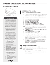
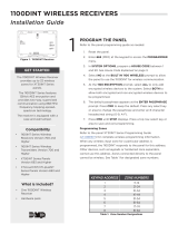
The 1100XINT Wireless Receiver
provides up to 100 wireless zones
for the XR150INT Series panels
and up to 500 wireless zones
for XR550INT Series panels. The
receiver features 128-bit AES
encryption.
The 1100XINT also provides two
way communication using 868
MHz frequency-hopping- spread-
spectrum technology and is
equipped with a case and wall
tamper.
Compatibility
• 1100INT Series Wireless Receivers
Version 700 and Higher
• 1100INT Series Wireless
Transmitters Version 700 and
Higher
• XR150INT/XR550INT Series
Panels Version 693 and Higher
What is Included?
• One 1100XINT Receiver
• Hardware Pack
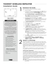
1PROGRAM THE PANEL
Refer to the panel programming guide as needed.
1. Reset the panel.
2. Enter 6653 (PROG).
3. In SYSTEM OPTIONS, program a HOUSE CODE between 1
and 50. See House Code Explained on page 3.
4. At the 1100 ENCRYPTION prompt, select ALL to only add
encrypted wireless devices to the system. Select BOTH to
allow both encrypted and non-encrypted wireless devices to
be programmed.
5. The default passphrase appears at the ENTER PASSPHRASE
prompt. Press CMD to keep the default. Press any select key
or area to change the passphrase and enter an 8-character
hexadecimal string (0-9, A-F).
6. In ZONE INFORMATION, enter a zone name and press CMD.
7. Select ZONE TYPE and press CMD.
8. At NEXT ZN?, select NO.
9. Select YES when WIRELESS? displays.
10. Enter the eight-digit SERIAL# and press CMD.
11. Enter the SUPRVSN TIME and press CMD.
12. At the NEXT ZN? prompt, select YES to finish programming
or select NO for additional programming options.
Programming Zones
Refer to the panel XR150INT/XR550INT Series Programming Guide
(LT-1232INT) for complete wireless programming information.
When any wireless input zone for a particular address is
programmed, the receiver responds to the panel for this address.
Other devices, such as keypads or hardwired zone expanders,
cannot use this address. Zones connected directly to the panel
cannot be wireless. See Table 1 for designated zone numbers.
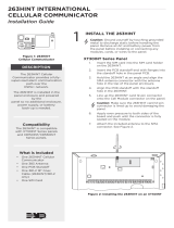
Figure 1: 1100XINT Receiver
ZONE NUMBERS DESIGNATIONS
400-449 1144INT Wireless Key Fobs
450-479 Slow Response Outputs (15 sec.)
480-499 Fast Response Outputs (1 sec.)
500-599 Wireless Devices (XR150INT)
500-999 Wireless Devices (XR550INT)
Table 1: Zone Number Designations

2 1100XINT INSTALLATION GUIDE | DIGITAL MONITORING PRODUCTS
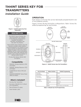
MOUNT THE 1100XINT RECEIVER
The receiver is equipped with a case and wall tamper. When the housing cover is removed, the case tamper
activates and the receiver sends a tamper trouble to the panel. To enable the tamper, see the following steps.
A two-position header is provided to disable the wall tamper. To disable the wall tamper, place the jumper
across the two pins of the header.
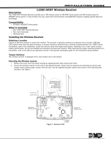
1. With the cover already removed, remove
the PCB from the housing to access the
tamper and mounting holes.
2. Mount the receiver on a flat surface using
the supplied screws. See Figure 2 for
mounting hole locations.
3. Use one of the provided screws to anchor
the housing in the wall tamper screw hole.
4. Snap the PCB back into the housing
attached to the wall. Observe LED
operation.
3
2The receiver’s mounting location should be centrally located between the 1100INT Series transmitters used
in the installation. The receiver can be extended up to 500 ft from the panel using 22 AWG or 1,000 ft using
18 AWG. Mount the receiver away from large metal objects. Do not use shielded wire between the panel and
receiver.
LED Survey Operation for 1100INT Series Transmitters
1100INT Series transmitters provide a survey operation that allows one person to confirm communication with
the wireless receiver or panel while the cover is removed. Follow the directions below to test communication of
the wireless transmitters:
1. Remove the transmitter’s cover.
2. Hold the transmitter in the exact desired location.
3. Press the tamper to send data to the wireless receiver and determine if communication is confirmed or
faulty.
Confirmed: If communication is confirmed, the survey LED turns on when data is sent to the wireless
receiver and o when acknowledgment is received.
Faulty: If communication is faulty, the LED remains on for several seconds or flashes multiple times
in quick succession. Relocate the transmitter or the wireless receiver until the LED confirms clear
communication. Proper communication between the transmitter and wireless receiver is verified when
each press or release of the tamper switch, the transmitter’s LED blinks immediately on and immediately
o.
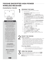
SELECT A LOCATION
Tamper Puck
Figure 2: Inside of the 1100XINT Housing
Mounting
Hole
Battery

1100XINT INSTALLATION GUIDE | DIGITAL MONITORING PRODUCTS 3
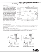
4POWER THE 1100XINT RECEIVER
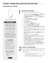
Connect the red, yellow, green, and black wires to the screw terminals on the receiver and connect the other
ends of the harness to the XBUS terminal on the panel. See Figure 3.
Note: The receiver can’t operate if it’s connected to the keypad bus.
ADDITIONAL INFORMATION
1100XINT LED Operation
The six labeled LEDs on the 1100XINT PCB display wireless receiver operation and activity. See Table 2 for LED
indications.
Note: The status LED light will remain solid red when wireless jamming is enabled or if there is a large amount of
RF activity in the vicinity of the receiver.
House Code Explained
The house code identifies the panel, receiver, and transmitters to each other. The receiver automatically sends the
specified house code to wireless transmitters when transmitter serial numbers are programmed into the panel. The
receiver only listens for transmissions using the specified house code or the programmed transmitters’ serial numbers.
Black
Green
Yellow
Red Can be extended
up to 500 ft
from the panel
using 22 AWG
or 1,000 ft
using 18 AWG
XR150INT/XR550INT
Series Panel
Battery Start
Power
LED
REC - Receive LED
XMT - Transmit LED
RF RX
RF TX
PANEL RX
PANEL TX
WALL
TAMPER
ENABLE
DISABLE
1100XINT
Receiver
Figure 3: Wiring The 1100XINT to the Panel
LED INDICATIONS
RF RX Flashes yellow to indicate data is being received from a transmitter.
RF TX Flashes green to indicate data is being sent to a transmitter.
PANEL RX Flashes yellow to indicate data is being received from a panel.
PANEL TX Flashes green to indicate data is being sent to the panel.
STATUS Solid red to indicate memory is being uploaded. Turns o when complete.
PWR Solid green to indicate there is power to the wireless receiver.
Table 2: 1100XINT LED Indications

Designed, engineered, and
manufactured in Springfield, MO
using U.S. and global components.
LT-1822INT 1.01 22133
INTRUSION • FIRE • ACCESS • NETWORKS
2500 North Partnership Boulevard
Springfield, Missouri 65803-8877
800.641.4282 | DMP.com
© 2022
1100XINT
WIRELESS RECEIVER
Specifications
Security Grade 2 Type B ACE
Environmental Class II
Operating Temperature 0°C - 49°C
32°F - 120°F
Relative Humidity 80%
Weight .23kg
Operating Voltage 8.0 to 14.0 VDC
Current Draw 25mA (average), 35mA (peak)
Frequency Range 863-869 MHz
Housing Material Flame retardant ABS
Dimensions 4.65”L x 3.1”W x 1.4”H
11.8 L x 7.9 W x 3.6 H cm
8.6” H / 21.8 H cm
Color White
Patents
U. S. Patent No. 7,239,236
International Certificates
Intertek (ETL)
EN 50130-4:2011 EMC - Product Family Standard.
Immunity Requirements for
Components of Fire, Intruder, and
Social Alarm Systems
EN 50130-5:2011 Alarm Systems. Environmental Test
Methods
EN 50131-1:2006+A1;A2 Alarm Systems. Intrusion and Hold-
up Systems. System Requirements
EN 50131-3:2009 Alarm Systems. Intrusion and Hold-
up Systems. Control and Indicating
Equipment
EN 50131-5-3:2017 Alarm Systems. Intrusion systems.
Requirements for Interconnections
Equipment using Radio Frequency
Techniques
EN 61000-3-2:2009+A1;A2 Limits - Limits for Harmonic Current
Emissions (Equipment Input Current
less than or equal to 16 A per Phase)
EN 61000-3-3:2013 Limits - Limitation of Voltage
Changes, Voltage Fluctuations and
Flicker in Public Low-Voltage Supply
Systems, for Equipment With Rather
Current less than or equal to 16 A
per Phase and Not Subject to
Conditional Connection
EN 61000-6-4:2018 Generic Standard - Emission
Standard for Industrial
Environments
R Y G B
TO PANEL
/