Page is loading ...

1
INSTALL THE 263HINT
Caution: Ground yourself by touching grounded
metal to discharge static before handling the
panel. Remove all AC and battery power from
the panel before installing or connecting any
modules, cards, or wires to the panel.
XT30INT Series Panel
1. Insert the SIM card into the SIM card holder
on the 263HINT.
2. Insert the PCB stando end with flanges into
the stando hole in the panel PCB.
3. Hold the 263HINT at an angle and align the
SMA antenna connector with the antenna
hole in the top of the panel enclosure.
4. Align the PCB stando with the stando
hole in the 263HINT.
5. Line up the 263HINT card 12-pin connector
onto the Cell Module connector on the panel.
Caution: Make sure the 263HINT card 12-pin
connector is lined up to avoid damaging the
panel.
6. Apply even pressure to both sides of the
board and push until the connector is fully
seated on the module.
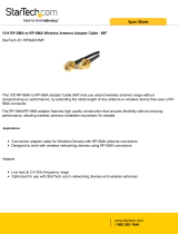
7. Attach the included antenna to the SMA
connector. See Figure 2.
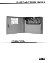
DESCRIPTION
65555
SIM
CARD
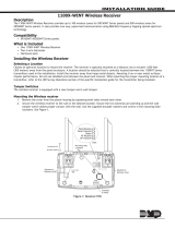
Figure 1: 263HINT
Cellular Communicator
263HINT INTERNATIONAL
CELLULAR COMMUNICATOR
Installation Guide
The 263HINT Cellular
Communicator provides a fully-
supervised alarm communication
path over the
HSPA+ network.
The 263HINT is installed in the
panel enclosure and powered
by the
panel so no additional enclosure,
power supply, or battery
back-up is needed.
Compatibility
The 263HINT is compatible
with XT30INT Series panels
and XR150INT/XR550INT
Series panels.
What is Included
• One 263HINT Cellular
Communicator
• One 383 Antenna
• One PCB Stando
• One 381-2 18" Coax
Cable (263HINT/381-2
only)
• One SIM Card
Figure 2: Installing the 263HINT on an XT30INT

2 DIGITAL MONITORING PRODUCTS | 263HINT INSTALLATION GUIDE
XR150INT/XR550INT Series Panel
If needed, the PCB can be removed from the enclosure to
allow you to place the cell module.
1. Insert the PCB stando end with flanges into the
stando hole in the panel PCB.
2. Align the PCB stando with the stando hole in
the 263HINT.
3. Line up the 263HINT card 12-pin connector onto
the Cell Module connector on the panel.
Caution: Make sure the 263HINT card 12-pin
connector is lined up to avoid damaging the panel.
There should be a space between the top of the
connector and the Ethernet port.
4. Apply even pressure to both sides of the board
and push until the connector is fully seated on the
module. See Figure 3.
5. Attach the 381-2 cable to the SMA connector.
6. Position one of the washers onto the 381-2 SMA
connector and push the threaded end through an
enclosure knockout. See Figure 3.
7. Position the second washer onto the threaded end
extending through the knockout and secure the
nut.
8. Attach the included 383 Antenna to the SMA
connector.
9. Attach the opposite end of the 381-2 Coax to the
SMA connector on the 263HINT. See Figure 2.
Note: As an alternative, an antenna coax can be
connected directly to the 263HINT SMA connector
when the coax enters the enclosure via conduit.
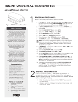
Figure 3: Installing the 263HINT
on an XR150/XR550
381-2
Coax
Cable
2
ACTIVATE THE 263HINT
Cellular service is required before you can use the 263HINT for signal transmission. The
263HINT comes ready for activation with SecureCom™ Wireless, LLC. If you are using a
SecureCom Wireless SIM card, use one of the following activation options. If you are using a
dierent type of SIM, follow your organization's activation process.
To activate a SecureCom Wireless SIM, verify that it has been added to the panel by using
Remote Link™, the Dealer Admin site (dealeradmin.securecomwireless.com), the Tech APP™,
or by calling DMP Customer Service (1-866-266-2826).
Remote Link Activation
1. In Remote Link panel communication programming, select Cellular Network as the
Communication Type and select the Activate button.
a.
In the Activate SIM/MEID window, enter the SIM number, found on the SIM card.
b. Select the rate plan for the 263HINT.
c. Select the
Activate
button at the bottom of the window.
2. After the 263HINT is installed at the site, use a keypad and enter the panel's
Diagnostics menu (2313).
a. Select
ACTIVATE CELL
by pressing a top row Select Key.
b. Press the button beneath
YES
on the next screen to activate the device.
Note:
The
ACTIVATE CELL
prompt will only display if a HSPA+ modem is installed. To
perform the cellular activation process from a keypad, the panel must be in contact
with a Verizon owned tower.
SMA Connector,
Nut, and Washers

263HINT INSTALLATION GUIDE | DIGITAL MONITORING PRODUCTS 3
Dealer Admin Activation
1. Navigate to the Dealer Admin site (dealeradmin.securecomwireless.com).
2. Select the appropriate customer from the Customer Dashboard.
3. Click Add System.
4. Enter a System Name.
5. Select an option from the System Type drop-down menu.
6. Select either Cellular or EASYconnect + Cell Backup in the Connection Type field.
7. Enter the SIM number found on the SIM card.
8. Click Get Status.
9. Enter the Account Number.
10. Select a Rate Plan and an SMS Package for the 263HINT.
11. Click Activate Cellular Device.
Tech APP Activation
1. Navigate to the Tech APP.
2. Tap Find a Customer then search for a customer.
3. Tap Add a System.
4. Enter a System Name.
5. Scan or enter the Serial #.
6. Select an option from the System Type drop-down menu.
7. Select either Cellular or EASYconnect + Cell Backup in the Connection Type field.
8. Enter the Account Number.
9. Enter the SIM number found on the SIM card.
10. Tap Get Status.
11. Select a Rate Plan and an SMS Package for the 263HINT.
12. Tap Activate Cellular Device.
3
TEST THE 263HINT
The panels provide a diagnostics function to test the communication integrity and cellular
signal strength of the 263HINT. To use diagnostics, reset the panel, enter the diagnostics code
2313 (DIAG) and press CMD for
XR150INT/XR550INT Series panels or 231 and press CMD for XT30INT Series panels.
Communication Status
Select COMM STATUS from the Diagnostics menu. The panel tests the 263HINT for the
following items:
Cellular Signal
Select CELL SIGNAL from the Diagnostics menu. The panel tests and indicates the strength of
the signal using a bar display. One bar indicates a weak signal and seven bars indicate a strong
signal. The signal strength is displayed as a -dBm value.
• 263HINT Installed • Cellular Tower Detected • 263HINT Registered
• 263HINT Operating • Connect Success • 263HINT Identified
• Communication Path Integrity

Designed, engineered, and
manufactured in Springfield, Missouri
using U.S. and global components.
© 2018 Digital Monitoring Products, Inc.
LT-1270INT 18114 1.01
INTRUSION • FIRE •ACCESS •NETWORKS
2500 North Partnership Boulevard
Springfield, Missouri 65803-8877
888.436.7832 | DMP.com
Specifications
Primary Power 12.0VDC from panel
Current Draw
Standby 24 mA
Alarm 28 mA
Compatibility
XT30INT Series panels
XR150INT/XR550INT Series panels
Accessories
381-2 18" Coax Cable
381-12 12' Coax Extension
381-25 25' Coax Extension
383 Antenna (included)
386 Outdoor Antenna Mounting Bracket
387-1 3dB Fiberglass Antenna w/Bracket
387-2 2dB Attack Enclosure Antenna
387-3 3dB MEG Antenna
Ordering Information
263HINT/381-2 International Cellular
Communicator with 18" Coax Cable
263HINT International Cellular Communicator
263HINT CELLULAR
COMMUNICATOR
65555
SIM
CARD
INTERNATIONAL CERTIFICATIONS
Security Grade: 3
Environmental Class: II
Intertek (ETL) Listed
EN 50130-4:2011+A1:2014 Alarm systems. Electromagnetic compatibility. Product family
standard: Immunity requirements for components of fire,
intruder, hold up, CCTV, access control and social alarm
systems.
EN 50130-5:2011 Alarm systems. Environmental test methods.
EN 50131-1:2006/A1:2009 Alarm systems. Intrusion and hold-up systems. System
requirements.
EN 50131-3:2009 Alarm systems. Intrusion and hold-up systems. Control and
indicating equipment.
EN 50136-1:2012 Alarm systems. Alarm transmission systems and equipment.
General requirements for alarm transmission systems.
EN 50136-2:2013 Alarm systems. Alarm transmission systems and equipment.
Requirements for Supervised Premises Transceiver (SPT).
EN 61000-3-2:2006+A1+A2 Electromagnetic compatibility (EMC) — Part 3 – 2: Limits for
harmonic current emissions.
EN 61000-3-3:2013 Electromagnetic compatibility (EMC)-Part 3-3:
Limits-Limitation of voltage changes, voltage fluctuations and
flicker in public low-voltage supply systems, for equipment
with rated current≤16 A per phase and not subject to
conditional connection.
EN 61000-6-4:2007 Emission standard for industrial environments.
/