Digital Monitoring Products XR150/XR550 International Compliance Guide
- Type
- Compliance Guide

COMPLIANCE LISTING GUIDE
XR150INT/XR550INT SERIES
INTERNATIONAL CONTROL PANEL

MODEL XR150INT/XR550INT SERIES
INTERNATIONAL COMPLIANCE GUIDE
© 2015 Digital Monitoring Products, Inc.
Information furnished by DMP is believed to be accurate and reliable.
This information is subject to change without notice. This information is subject to change without notice.

XR150/XR550 Series International Listing Guide Digital Monitoring Products
iii
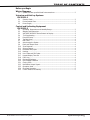
TABLE OF CONTENTS
Before you Begin
Wiring Diagrams
1.1 SpecicandNon-specicWiredInterconnections ............................................. 2
Intrusion and Hold-up Systems
EN 50131-1
2.1 Security Grade ...............................................................................................3
2.2 Environmental Class .......................................................................................3
2.3 Power Supply ................................................................................................3
Control and Indicating Equipment
EN 50131-3
3.1 Operating Temperature and Humidity Range ....................................................3
3.2 WeightsandDimensions ................................................................................3
3.3 XR150INT/XR550INTSeriesStatusListDisplay ................................................3
3.4 734 Programming ..........................................................................................4
3.5 Entry/ExitDelay ............................................................................................4
3.6 Transmit Delay ..............................................................................................4
3.7 Bell Cutoff .....................................................................................................4
3.8 Auto Arming the System ................................................................................4
3.9 Fault and Tamper Alerts ................................................................................. 4
3.10 ZoneExpander ..............................................................................................4
3.11 Swinger Bypass .............................................................................................4
3.14 DisarmedShort/Open ....................................................................................4
3.15 Masking ........................................................................................................4
3.16 UserCodesandPINCodes ............................................................................. 4
3.17 Keypad Display Time Out ...............................................................................4
3.18 EventLog .....................................................................................................4
3.19 Discharge/Recharge .......................................................................................4
3.20 Over Voltage Protection .................................................................................4
3.21 Closing Code .................................................................................................4
3.22 NoticationOutputSignals .............................................................................5
3.23 Operation Mode .............................................................................................5
3.24 Dual Path Operation....................................................................................... 5
3.25 Control Panel Unav ailability ...........................................................................5

XR150/XR550 Series International Listing Guide Digital Monitoring Products
1
PROGRAMMING OPTIONS
Before you Begin
This guide provides compliance information for the DMP XR150INT/XR550INT Series International Control Panels. After
this Introduction, the remaining sections describe the functions along with the available options. Before starting, we
recommend that you read through the contents of this guide. The information contained here allows you to quickly learn
the operation, functionality, and programming options of the panel to meet specic applications.
This guide covers all the requirements for the following panels:
• XR150INT Series
• XR550INT Series

Digital Monitoring Products XR150/XR550 Series International Listing Guide
2
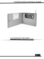
WIRING DIAGRAMS
Wiring Diagrams
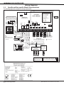
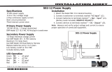
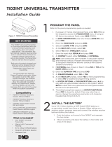
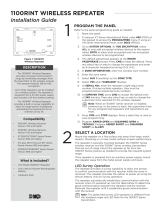
1.1 SpecicandNon-specicWiredInterconnections
The following pages show examples for wiring requirements.
AC
1 2 3 4 5 6 7 8 10 11 12 13 14 15 16 17 18 199 20 21 22 23 24 25 26 27 28
+B BELL GND SMK GNDRED YEL GRN BLK Z1 Z2 Z3 Z4 Z5 Z6 Z7 Z8 Z9+ Z9– Z10+ Z10–AC –B GND GND GNDGND
Auxiliary Power
Total current combined from terminals
7, 11, 25, 27, XBUS and LX500-LX900
1.5 Amp Max 13.8 VDC to 10.2 VDC
LX800
LX900
J4
Tamper
K6 K7
Output 1 Output 2
J3
Phone Line
Battery
Start
J8
J16
Reset
Out1 Out2
Outputs 3-6
J11
3
4
5
6
J2
OVC
XR550INT Series
International Panel
LX500
LX700
XBUS
J13
J14 J9 J15 J19J17
J24
Form C Relays (J2)
Output Color Code–Model 431 Harness
Output 2 N/O Orange/White
Output 2 Com White/Gray
Output 2 N/C Violet/White
Output 1 N/O Orange
Output 1 Com Gray
Output 1 N/C Violet
Annunciator Outputs (J11)
Output Color Code
Output 3 Red
Output 4 Yellow
Output 5 Green
Output 6 Black
ss
J12 75VA
50VA
Listed Resistors
1.0k Ohm - DMP Model 311
3.3k Ohm - DMP Model 309
10K Ohm - DMP Model 308
LX600
Tamper
16 to 18 gauge wire
Maximum AC Wire distance
with 16 gauge wire: 70 feet
with 18 gauge wire: 40 feet
RED
BLACK
Cold Water
Pipe Earth
Ground
Bell
3.3k Ohm
Resistor DMP
Model 309
3.3k Ohm
Resistor DMP
Model 309
s
= Supervised Circuit
Zone
9
Zone
10
22 gauge minimum
22 gauge minimum
22 gauge minimum
22 gauge minimum
RED
YELLOW
GREEN
BLACK
Zone Expander
Models 714-8INT,
714-16INT
20mA @ 12 VDC
RED
YELLOW
GREEN
BLACK
s
Dual
1k
Ohm
Zone Expander
(up to 8 zones)
Model 712-8INT
19mA @ 12 VDC
1k
Ohm
Earth Ground
s s s s
sss
s
s
s
s
s
s
¼"
AC Wiring must be in conduit and exit
out the left side of the enclosure.
Wiring on terminals 5 through 22 must
exit right and maintain 1/4" separation
from the AC and battery positive wiring.
Dual
1k
Ohm
Dual
1k
Ohm
Dual
1k
Ohm
Dual
1k
Ohm
Dual
1k
Ohm
Dual
1k
Ohm
Dual
1k
Ohm
ssssssss
ssssssss
Dual
1k
Ohm
ss
Dual
1k
Ohm
ss
Dual
1k
Ohm
ss
Dual
1k
Ohm
ss
s
Model 324INT 230V 100VA
CAUTION: DO NOT USE LOOPED WIRE
UNDER TERMINALS. BREAK WIRE RUN TO
PROVIDE SUPERVISION OF CONNECTIONS.
WARNING: Incorrect
connections may cause
damage to the unit.
Bell cutoff time
range is 2 to 15
minutes, non-coded.
Bell
12 VDC
Default cutoff time 15 min.
Minimum cutoff time 2 min.
1.5 Amp Max
Conduit
INPUT OUTPUT
GROUND

XR150/XR550 Series International Listing Guide Digital Monitoring Products
3
PROGRAMMING OPTIONS
Intrusion and Hold-up Systems
EN 50131-1
2.1 Security Grade
The Model XR150INT/XR550INT Series International provides a Security Grade 3 fullling Options A, B, or C.
2.2 Environmental Class
The Model XR150INT/XR550INT Series International provides Environmental Class II.
2.3 Power Supply
The Model XR150INT/XR550INT Series International employs a Type A power supply.
Control and Indicating Equipment
EN 50131-3
3.1 Operating Temperature and Humidity Range
The XR150INT/XR550INT Series International is suitable for temperatures ranging from 0°C to 49°C and a relative
humidity of 80%.
3.2 Weights and Dimensions
The XR150INT/XR550INT PCB Series International weighs 1.7 kg and is 26 cm wide by 14 cm high.
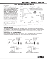
3.3 XR150INT/XR550INT Series Status List Display
Priority Category Description Latches
Display
1Fire Zone Alarms FI and FV zone alarms Y
2Emergency Alarms EM zone alarms Y
3 Fire troubles and Supervisory
alarms and troubles
FI, FV and EM troubles
SV alarms and troubles
Y
4Burglary Zone Alarms NT, DY, EX and AR Zone Alarms N
5 System Messages Walk Test
Transmitter Missing
Transmitter Low Battery
Wireless Jamming
Wireless Keypad Missing, Tamper, AC Power, Low
Battery, Wireless Keypad Trouble,
Z-Wave Lock Low Battery
Any other System Monitor Troubles
N
6 Late to Close Message System has not armed as Scheduled N
7 All other Zone Messages Key Fob Alarm, Low Battery, Missing, Trouble
Output Alarm, Low Battery, Missing, Trouble
Door Propped
Zone Monitor
Day Zone Alert
Alarms on PN, A1 and A2
N
8 Armed or Ready Status Status of the Panel N
9Day and Time Current Date and Time N
10 Today’s Current Weather Today’s Weather N
11 Tomorrow’s Weather Tomorrow’s Weather N
14 Keypad Bus Device Message Device Missing
Device Tamper
N

Digital Monitoring Products XR150/XR550 Series International Listing Guide
4
OPERATION
3.4 734 Programming
After initial installation, changes to 734/734N programming must be made through the device setup menu in panel
programming.
3.5 Entry/Exit Delay
In System Options, set Entry Delay 30 - 45 seconds. In Area Information, set Exit Delay to 30 - 45 seconds.
3.6 Transmit Delay
In Communications, Transmit Delay must be set the same as Entry Delay in System Options.
3.7 Bell Cutoff
In Bell Options, Bell Cutoff must be set to 2 - 15 minutes.
3.8 Auto Arming the System
In Area Information, Closing Check must be ON when using Auto Arm. When arming, Closing Time! is displayed
for 10 minutes and the keypad sounds. Bad zones are processed according to the Bad Zones programming in Area
Information. Other troubles are automatically overridden.
3.9 Fault and Tamper Alerts
When a fault or tamper alert is listed in the status list, only the Service User can arm the system until the fault or
tamper is corrected.
3.10 Zone Expander
When using a zone expander module, one zone of the module must be used as tamper supervision.
3.11 Swinger Bypass
In System Options, SWGRBYPS TRIPS: must be set to 3 or higher.
3.14 Disarmed Short/Open
In Zone Programming, the Alarm Action message sent to Central Station for Disarm Short and Disarm Open must be
set to T for Trouble Alert.
3.15 Masking
Connect a zone to the masking contacts of a device. Name the zone in Zone Programming “X Detector Masking”,
where X is the name of the detector zone and for Alarm Action, set the Transmit Message to T (Trouble) for both
Disarmed and Armed actions.
3.16 User Codes and PIN Codes
User Codes and PIN Codes must be at least 5-digits (0 - 9) for a total of 100,000 possible combinations.
3.17 Keypad Display Time Out
A valid User Code is required to be entered to display the Status List. The display will time out in 60 seconds with no
key presses. A valid User Code will be required to be entered again to view list.
3.18 Event Log
Events are stored in non volatile memory with greater than 100 year data retention.
Manufacturer part number SST39VF3202B.
3.19 Discharge/Recharge
The XR150INT/XR550INT Series International battery charging circuit oat charges at 13.8 Vdc at a maximum current
of 1.5 Amps using a 100VA transformer, Listed below are the various battery voltage level conditions:
Battery Trouble: Below 11.2 Vdc
Battery Cutoff: Below 10.2 Vdc
Battery Restored: Above 12.6 Vdc
The panel disconnects the battery any time the battery voltage drops below 10.2 Vdc. This prevents battery deep
discharge damage. The XR150INT/XR550INT will charge a maximum of 45Ah batteries to 80% in 24 hours.
3.20 Over Voltage Protection
Output circuitry is designed to limit voltage to 15V.
3.21 Closing Code
In System Options, set Closing Code to YES.

800-641-4282
INTRUSION • FIRE • ACCESS • NETWORKS
www.dmp.com 2500 North Partnership Boulevard
Designed, Engineered and
Assembled in U.S.A. Springeld, Missouri 65803-8877
LT-1330INT 1.01 © 2016 Digital Monitoring Products, Inc.
16204
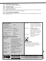
Documentation
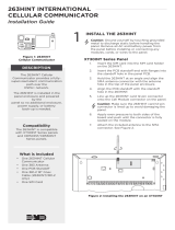
Power Supply Type A
Security Grade 3
Environmental Class II
EN 50131-1
Notication Requirements Grade 3
Options A,B, or C
Operating Temperature 0°C - 49°C
32°F - 120°F
Relative Humidity 80%
Weight 1.7 kg)
Dimensions 26W x 14H cm
Max Ripple Voltage 50mV
InternationalCertications
Intertek (ETL)
EN 50130-4 EMC Product Family Standard:
Immunity Requirements for
Components of Fire, Intruder and
Social Alarm Systems
EN 50130-5 Environmental Standards
EN 50131-1:2006+A1 Intrusion and hold-up systems
EN 50131-3:2009 Control and Indicating Equipment
EN 50131-5 Interconnections Equipment using
Radio Frequency techniques
EN 50131-6:2008 Power Supplies
EN 50133-1:1997 Access Control Systems
EN 50136-1 Alarm Transmission Systems and
Equipment
EN 50136-2:2013 Supervised Premises Transceiver
EN 50136-3 Receiving Centre Transceiver
EN 50131-6 Power Supplies
EN 61000-3-2 Limits - Limits for Harmonic
Current Emissions (Equip.Input
Current up to and Including 16 A
per Phase) Includes A1 & A2 July
1, 2009
EN 61000-3-3 Limitation of Voltage
Fluctuations & Flicker in Low-
Voltage Supply Systems for
Equip. with Rated Current Less
Than or Equal to 16 A per Phase
& Not Subject to Conditional
Connection
EN 61000-6-4 Generic Standards - Emission
Standard for Industrial
Environments
Export Control
The XR550INT with encryption uses AES
encryption and any export beyond the United
States must be in accordance with Export
Administration Regulations.
3.22 NoticationOutputSignals
Provides Hold-up, Tamper, and Intrusion notications.
3.23 Operation Mode
Stores and forwards all messages to SCS-VR or SCS-1R.
3.24 Dual Path Operation
Communication takes place on the primary path with backup paths being used only when the primary path fails or
when the backup path is being used to send duplicate messages.
3.25 Control Panel Unavailability
The control panel is considered unavailable when the system message 16 panel NOT RESPONDING is generated by
the central station receiver.
-
 1
1
-
 2
2
-
 3
3
-
 4
4
-
 5
5
-
 6
6
-
 7
7
-
 8
8


Digital Monitoring Products XR150/XR550 International Compliance Guide
- Type
- Compliance Guide
Ask a question and I''ll find the answer in the document
Finding information in a document is now easier with AI
Related papers
-
 DMP Electronics XR550 series Installation guide
-
 Digital Monitoring Products XR150/XR550 International Installation & Programming Guides
-
 Digital Monitoring Products 712-8INT Zone Expansion Module Installation guide
-
 Digital Monitoring Products 502 User guide
-
 Digital Monitoring Products 734N Series Wiegand Interface Modules Programming Guide
-
 DMP Electronics 734N Wiegand Interface Module Installation guide
-
 Digital Monitoring Products 7000 International Series Thinline Keypad Installation & Programming Guides
-
 Digital Monitoring Products 734 International Access Control Module Installation & Programming Guides
-
 Digital Monitoring Products 1100XINT Wireless Receiver Installation & Programming Guides
-
 Digital Monitoring Products 1103INT Universal Transmitter Installation & Programming Guides


Other documents
-
 DMP Electronics XR550INT Series Installation guide
-
DMP LT-1232CAN Installation guide
-
 DMP Electronics 734N-POE Installation And Programming Manual
-
 DMP Electronics Wiegand 734N Installation guide
-
 DMP Electronics 263HINT Installation guide
-
DMP Electronics International Thinline 7063-WINT Installation And Programming Manual
-
 DMP Electronics 1100RINT Installation guide
-
 DMP Electronics 9862-W Installation And Programming Manual
-
 DMP Electronics 734 Installation And Programming Manual
-
 DMP Electronics 1144INT Series Installation guide


