Page is loading ...

INSTALLATION GUIDE
1100X-WINT Wireless Receiver
Description
The 1100X-WINT Wireless Receiver provides up to 100 wireless zones for XR150INT Series panels and 500 wireless zones for
XR550INT Series panels. It also provides two-way, supervised communication using 868 MHz frequency hopping-spread-spectrum
technology.
Compatibility
• XR150INT/XR550INT Series panels
What is Included
• One 1100X-WINT Wireless Receiver
• Two 4-wire harnesses
• Hardware pack
Installing the Wireless Receiver
Selecting a Location
Choose an optimum location to mount the receiver. The receiver is typically mounted at a distance not to exceed 1,000 feet
(305 meters) away from the panel enclosure. A location should be selected that is centrally located between the 1100INT Series
transmitters used in the installation. Install the receiver away from large metal objects. Mounting it on or near metal surfaces
impairs performance. Do not use shielded wire between the panel and receiver. When selecting the proper mounting location of a
transmitter, refer to the LED Survey Operation section of the specic installation guide for the transmitter being installed.
Tamper Switches
The wireless receiver is equipped with a case tamper and a wall tamper.
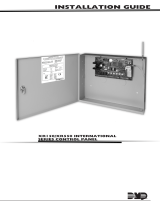
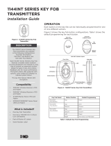
Mounting the Wireless receiver
1. Remove the cover from the plastic housing by squeezing both sides toward each other.
2. Secure the wireless receiver to the wall in the desired location. Ensure the two antennas are pointing up and the wall
tamper switch makes proper contact with the wall. Use the supplied shoulder washers and screws in the mounting hole
locations. See Figure 1.
U10
U11
1
PANEL
Panel Receive
Panel Transmit
Status
RF Receive
RF Transmit
1
U8 Y1
L17
1
Panel Receive
Panel Transmit
Status
RF Receive
RF Transmit
Mounting Hole
Locations
LEDs
Squeeze to
Remove Cover
Mounting Screw
Shoulder Washer
Tamper
Switch
2-pin Header
Squeeze to
Remove Cover
Connects
to Panel
Figure 1: Receiver PCB

Digital Monitoring Products 1100X-WINT Wireless Receiver Installation Guide
2
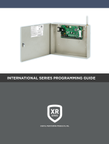
Wireless Bus Connection
On XR150INT/XR550INT Series panels, the 1100X-WINT interfaces using the on-board X-Bus connection.
Note: The wireless receiver cannot operate if it is connected to the Keypad Bus.
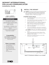
Harness Connection to XR150INT/XR550INT Series Panels
Use the XR150INT/XR550INT Series International Control Panel Programming Guide (LT-1232INT), Figure 2, and the following steps
to connect the panel and wireless receiver.
1. Connect the PANEL header on the wireless receiver to the XR150INT/XR550INT panel X-BUS header.
2. After power-up, briey reset the panel using the RESET jumper to activate wireless zone operation.
3. In System Options, program the House Code (1-50).
4. Snap the cover back on the unit. The panel immediately recognizes the wireless receiver if the panel is programmed with
a house code.
Figure 2: XR150INT/XR550INT DMP Wireless Bus Connection
Wireless Receiver Operation
The wireless receiver automatically sends the panel house code to wireless transmitters when the unique transmitter serial
number is programmed into the panel. The house code identies the panel, wireless receiver, and transmitters to each other. The
wireless receiver only listens for transmissions using the specied house code and/or programmed transmitter serial number.
Note: When setting up a wireless system, it is recommended to program zones and connect the wireless receiver before installing
batteries in the transmitters.
Transmitters can be programmed for supervised operation. When programmed as supervised, the transmitter must communicate
with the wireless receiver within the programmed number of minutes. If the transmitter fails to communicate, the panel displays
a missing condition.
When a wireless receiver is installed, powered up, or the panel is reset, the supervision time for transmitters is reset. If the
wireless receiver has been powered down for more than one hour, wireless transmitters may take up to an additional hour to send
a supervision message unless tripped, tampered, or powered up. This operation extends battery life for transmitters. A missing
message may display on the keypad until the transmitter sends a supervision message.
When any wireless zone programming is changed in the panel, wireless receiver zone programming is updated when exiting panel
programming. During the update, all wireless zones display as normal for approximately one minute, regardless of the actual
state of the wireless device(s).
Black
Green
Yellow
Red
Can be extended
up to 100 feet
from the panel
using 22 AWG
or 250 feet
usin
g
18 AWG
XR150INT/XR550INT
Series Panel
Battery Start
Power
LED
U5
1
Power
RXD
TXD
Status
RF RXD
RF TXD
J4
1
U4
1
U7
J1
1
1100X-WINT
Receiver
REC - Receive LED
XMT - Transmit LED
PANEL

1100X-WINT Wireless Receiver Installation Guide Digital Monitoring Products
3
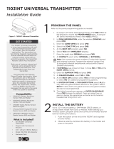
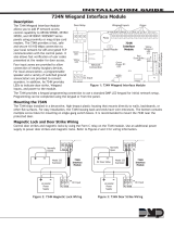
LED Operation
Six LEDs display wireless receiver operation and activity. Refer to the table below as required.
PCB LEDS LABEL OPERATION
Power
RXD
TXD
Status
RF RXD
RF TXD
POWER Steady green to indicate there is power to the wireless receiver.
RXD Flashes yellow to indicate data is being received from the panel.
TXD Flashes green to indicate data is being sent to the panel.
STATUS Steady red to indicate memory upload. O when upload is complete.
RF RXD Flashes yellow to indicate data is being received from a transmitter.
RF TXD Flashes green to indicate data is being sent to a transmitter.
Zone Conguration
Refer to the panel XR150INT/XR550INT Series International Programming Guide (LT-1232INT) for complete wireless programming
information.
When any wireless input zone for a particular address is programmed, the 1100X-WINT responds to the panel for this address.
Other devices, such as keypads or hardwired zone expanders, cannot use this address. Zones connected directly to the panel
cannot be wireless.
ZONE NUMBERS DESIGNATIONS
400-449 1144 Wireless Key Fobs
450-474 Slow Response Outputs (15 sec)
480-499 Fast Response Outputs (1 sec)
500-599 Wireless Devices (XR150INT)
500-999 Wireless Devices (XR550INT)
Transmitter Survey LED Operation
DMP 1100INT Series International transmitters provide a survey capability that allows one person to conrm that each transmitter
is communicating with the wireless receiver or panel. This allows you to easily determine the best location for the transmitters
and the wireless receiver when you are developing a site map of the system.
Check Location Using the Survey LED
1. Remove the transmitter’s cover.
2. Hold the transmitter in the exact desired location.
3. Press the tamper switch to send data to the wireless receiver and determine if communication is conrmed or faulty.
Conrmed
If communication is conrmed, the survey LED turns on when data is sent to the wireless receiver and o when
acknowledgement is received.
Faulty
If communication is faulty, the LED remains on for several seconds or ashes multiple times in quick succession.
Relocate the transmitter or the wireless receiver until the LED conrms clear communication. Proper communication
between the transmitter and wireless receiver is veried when for each press or release of the tamper switch, the
transmitter’s LED blinks immediately on and immediately o.

8 66-266-2826
INTRUSION • FIRE • ACCESS • NETWORKS
DMP.com 2500 North Partnership Boulevard
Designed, Engineered and
Assembled in U.S.A. Springeld, Missouri 65803-8877
LT-0708INT 18091 © 2018 Digital Monitoring Products, Inc.
International Certications
EN 50130-4:2011+A1:2014 Alarm systems. Electromagnetic compatibility. Product family standard: Immunity
requirements for components of re, intruder, hold up, CCTV, access control and
social alarm systems.
EN 61000-6-3:2007 Electromagnetic compatibility (EMC). Generic standards. Emission standard for
residential, commercial and light-industrial environments.
Specications
Operating Voltage 8.0 to 14.0VDC
Current Draw 46mA
RF Power Rating 27mW
Frequency Range 863-869 MHz
Dimensions
Receiver Housing 4.65” L x 3.1” W x 1.4” H
11.8 L x 7.9 W x 3.6 H cm
Antennas 8.6” H / 21.8 H cm
Color White
Housing Material Flame retardant ABS
Patents
U. S. Patent No. 7,239,236
Panel Compatibility
XR150INT/XR550INT Series panel
/