Page is loading ...

INSTALLATION GUIDE
1100INT Series Key Fob Transmitters
Description
The DMP 1100INT Series Wireless Key Fob transmitters are available in a Four-Button (1145-4-B-INT), Two-Button
(1145-2-B-INT), or One-Button (1145-1-B-INT) arrangement and are designed to be clipped to a key ring or lanyard.
Key Fob features include a durable water resistant housing, ergonomic button design for ease of use, and a status
feedback LED for visual conrmation. The button status LED responds with specic color-coded LED displays to
indicate system status.
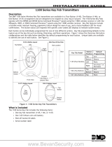
Each button can be individually programmed for one of nine different actions. Key fob programming defaults to the
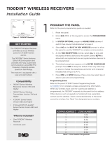
typical use of the key fob such as Arming, Disarming, and Panic operations. Figure 1 shows the three key fob button
congurations and the table below identies the default programming for each button. Unique labels are available
to identify the use of each button. See Figure 2.
Connect
Key Ring or
Lanyard Here
LED
Front View
Side View All Key Fobs
Left
Button
Top Button
Right
Button
Bottom
Button
Front Back
Slot Location
1145-2-B-INT
2-Button Layout
1145-1-B-INT
1-Button Layout
Top
Button
Bottom
Button
1145-4-B-INT
4-Button Layout
One
(Top)
Button
Compatibility
• All DMP 1100INT Series International Wireless Receivers and panels
What is Included
The 1100INT Series Key Fob includes the following items:
• One key fob transmitter (1145-1-B-INT, 1145-2-B-INT, or 1145-4-B-INT)
• One 3.0V lithium coin cell battery
• Peel-off button ID labels
• Serial number label
Key Fob Model Button
Position
Default
Programming
1145-4-B-INT (Four-Button)
To p Arm
Bottom Disarm
Left Panic
Right Arm Area 1 or
Perimeter
1145-2-B-INT (Two-Button) To p Arm
Bottom Disarm
1145-1-B-INT (One-Button) Top Panic
Figure 1: 1100INT Series Key Fob Transmitters

Digital Monitoring Products 1100INT Series International Key Fob Installation Guide
2
Transmitter Serial Number
For your convenience, an additional pre-printed serial number label is included. Prior to programming the device,
record the serial number or place the pre-printed serial number label on the 1100INT Series Key Fob Programming
Sheet (LT-0706INT) included with the wireless receiver. This number is required during programming.
Programming the Key Fob in the Panel
Refer to the panel programming guide and 1100INT International Series Key Fob Programming Sheet (LT-0706INT)
as needed. Program the key fob as a zone in Zone Information during panel programming. At the Serial Number
prompt, enter the eight-digit serial number, including the leading zero. Continue to program the zone as directed
in the panel programming guide. Should the default button operation need to be changed, the buttons can be
reprogrammed to operate as needed in panel zone programming.
Note: As an option, the key fob may be programmed to be supervised. When a receiver is installed, powered up, or
the panel is reset, the supervision time for transmitters, including key fobs is reset. If the receiver has been
powered down for more than one hour, wireless transmitters may take up to an additional hour to send a
supervision message unless a button is pressed. If programmed, this operation extends battery life. A missing
message may display on the keypad until the key fob sends a supervision message.
Labeling the Key Fob for Use
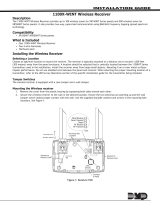
Attach the key fob transmitter to any key ring or lanyard. Select the peel-off labels that display the programming for
each button and place them onto the corresponding key fob buttons for identication. See Figure 2. For easier label
installation, use a small at head screwdriver or X-acto knife to select the label and apply it to the proper button
location as shown in Figure 1. Button labels can be changed if programming is changed.
LED Status Operation
Depending on the programmed action of a key fob button, the Status LED turns on to acknowledge a button press or
to indicate the armed state of the system.
• When the button is programmed for Panic, Panic 2, Emergency, Emergency 2, Output, or Sensor Reset, a 1/2
second Green ash occurs to acknowledge the button press.
• When the button is programmed for Arm, Disarm, Toggle arm/disarm, or Status, the system armed status is
received by the key fob and the LED pulses once as shown in the table below.
LED Color Duration Description
Red 2.0 Seconds All System On
Green 2.0 Seconds All System Off
Green/Red 2.0 Seconds System On (Some Areas Armed)
When a button programmed as Unused is pressed, the LED does not operate.
Note: For best operation, allow the LED to turn on and then turn off before pressing another button. The key fob
may not complete sending the signal for the button press if another button is pressed too soon.
Optional
Small or
Large
Labels are
available.
Figure 2: Button Labels

1100INT Series International Key Fob Installation Guide Digital Monitoring Products
3
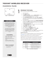
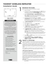
Replacing the Battery
Observe polarity when installing the battery. Use only 3.0V coin cell
batteries, DMP Model CR2032, or the equivalent CR2032 battery from
a local retail outlet.
1. Insert a small at head screwdriver into the slot at the key fob
end opposite the key ring and twist to separate the key fob
front and back sections.
2. Push and slide the old battery out of the holder in the direction
of the arrow to remove it. See Figure 3.
3. Verify the positive side of the battery is up.
4. Slide the new 3.0V Lithium battery into the holder and push into
place.
5. Snap the front and back sections back together.
6. Perform a Sensor Reset to clear LOBAT from the keypad screen.
Sensor Reset to Clear LOBAT
1. Press 2 and hold for two seconds on the keypad.
2. Enter your user code if required.
3. The keypad displays SENSORS OFF followed by SENSORS ON.
Caution: Properly dispose of used batteries. Do not
recharge, disassemble, heat above 212°F (100°C), or
incinerate. Risk of re, explosion, and burns.
Battery Life Expectancy
Typical battery life expectancy for DMP Model 1100INT Series Key Fobs is 1 to 1.5 years. DMP wireless equipment
uses two-way communication to extend battery life.
The following situations can reduce battery life expectancy:
• If a receiver is unplugged, too far away, or not installed.
Note: Transmitters continue to send supervision messages until a receiver returns an acknowledgement.
After an hour the transmitter only attempts a supervision message every 60 minutes.
• Frequent transmissions, such as pressing a button multiple times.
The following situation can extend battery life expectancy:
• Extend transmitter supervision time in panel programming.
• Infrequent button presses.
Figure 3: 1100INT Series Battery Location
Battery
Inside Battery
Compartment
Key Fob Front
Slot
Push Battery
Edge to Slide
Battery Out
Insert Battery
with Positive
Side Up

LT-0703INT © 2015 Digital Monitoring Products, Inc.
800-641-4282
www.dmp.com
Designed, Engineered and
Assembled in U.S.A.
INTRUSION • FIRE • ACCESS • NETWORKS
2500 North Partnership Boulevard
Springfield, Missouri 65803-8877
15315
Panel Compatibility
1100XINT Wireless Receiver
1100DINT Wireless Receiver
XT30INT Series panel
XR150INT/XR550INT Series panel
Specications
Battery
Life Expectancy 1 to 1.5 years
Type 3.0V lithium CR2032
See Battery Life Expectancy for full details.
Frequency Range: 863-869 MHz
Dimensions
1.98” H x 1.98” W x 0.6” D
5 H x 5 W x 1.5 D cm
Color Black
Housing Material ABS Plastic
Patents
U. S. Patent No. 7,239,236
/