Page is loading ...

DIGITAL MONITORING PRODUCTS, INC.
INTERNATIONAL SERIES PROGRAMMING GUIDE

B XR150/XR550 SERIES PROGRAMMING GUIDE | DIGITAL MONITORING PRODUCTS
MODEL XR150INT/XR550INT SERIES
PROGRAMMING GUIDE
Contains programming instructions for use with the
Model XR150INT/XR550INT Series Control Panels.
When using the XR150INT/XR550INT Series panel for any listing organization’s approved methods, refer
to the Compliance Listing Guide (LT-1330INT). This document outlines the installation and programming
requirements of all applications for which XR150INT/XR550INT Series control panels are approved.
© 2021 Digital Monitoring Products, Inc.
Information furnished by DMP is believed to be accurate and reliable.
This information is subject to change without notice.

XR150/XR550 SERIES PROGRAMMING GUIDE | DIGITAL MONITORING PRODUCTS I
INTRODUCTION ......................................1
XR International Series Programming
Information ............................................................................ 1
Getting Started .................................................................... 1
Accessing the User Menu ................................................. 1
Encrypted Communications (XR550INT with
Encryption Only) ................................................................. 1
Programmer Operation ..................................................... 2
Programmer Lockout Codes ........................................... 2
Reset Timeout ...................................................................... 2
Keypads .................................................................................. 2
Special Keys........................................................................... 2
Entering Alpha Characters .............................................. 3
Entering Non-Alpha Characters .................................... 3
Keypad Displays Current Programming ..................... 4
Multiple Displays .................................................................. 4
Asterisks in Programming ................................................ 4
Compliance Instructions ................................................... 4
INITIALIZATION ......................................5
Initialization ........................................................................... 5
Clear All Memory ................................................................. 5
Clear All Codes ..................................................................... 5
Clear All Schedules ............................................................. 5
Clear Display Events Memory ......................................... 5
Clear Zone Information ..................................................... 5
Clear Area Information ...................................................... 5
Clear Output Information ................................................. 5
Clear Communication and Remote Options ............. 5
Clear Wi-Fi ............................................................................. 5
Set to Factory Defaults ..................................................... 5
Communication .................................................................... 6
Account Number ................................................................. 6
Transmit Delay ...................................................................... 6
Communication Path ......................................................... 6
Communication Type ......................................................... 6
Test Report ............................................................................ 6
Test Frequency ..................................................................... 7
Test Day ................................................................................... 7
Test Time ................................................................................. 7
Check In .................................................................................. 7
Fail Time .................................................................................. 7
Encryption (XR550INT with Encryption Only) ........ 7
IPV6 Address ........................................................................ 7
Receiver IP ............................................................................. 8
Receiver Port ........................................................................ 8
First Telephone Number ................................................... 8
Second Telephone Number ............................................. 8
APN ........................................................................................... 8
Fail Test Hours ...................................................................... 8
Protocol ................................................................................... 8
Retry Seconds ...................................................................... 8
Substitution Code ............................................................... 9
893A ......................................................................................... 9
Alarm Switch ......................................................................... 9
Duplicate Alarms ................................................................. 9
Alarm Reports ...................................................................... 9
Supervisory/Trouble Reports ......................................... 9
Opening/Closing and User Reports ............................. 10
Door Access Report ........................................................... 10
Panic Test (Network Only)............................................... 10
Send Communication Trouble ........................................ 10
Send Path Information ...................................................... 10
NETWORK OPTIONS .............................. 11
Wi-Fi Setup ............................................................................ 11
WPS .......................................................................................... 11
List ............................................................................................. 11
Manual ..................................................................................... 11
Test ............................................................................................ 12
Wireless Security Type ...................................................... 12
Wireless Network Key ....................................................... 12
IPV6 .......................................................................................... 12
DHCP ........................................................................................ 12

II XR150/XR550 SERIES PROGRAMMING GUIDE | DIGITAL MONITORING PRODUCTS
Local IP Address ................................................................. 12
Gateway Address ................................................................ 12
Subnet Mask .......................................................................... 12
DNS Server............................................................................. 12
Passphrase (XR550INT with Encryption Only) ....... 13
DEVICE SETUP ........................................14
Device Setup ......................................................................... 14
Custom Card Definitions .................................................. 14
Wiegand Code Length ...................................................... 14
Site Code Position............................................................... 14
Site Code Length ................................................................. 14
User Code Position ............................................................. 14
User Code Length ............................................................... 14
Require Site Code ............................................................... 14
Number of User Code Digits ........................................... 15
Device Number .................................................................... 15
Device Name ......................................................................... 16
Device Type ........................................................................... 16
Private Door .......................................................................... 16
Device Communication Type .......................................... 16
Serial Number ....................................................................... 17
Supervision Time ................................................................. 17
Access Areas ......................................................................... 17
Egress Areas .......................................................................... 17
Display Areas ........................................................................ 17
Strike Time ............................................................................. 18
Strike Delay ............................................................................ 18
Fire Exit Release .................................................................. 19
Public Door ............................................................................ 19
Output Group ....................................................................... 19
Schedule Override .............................................................. 19
Auto Force Arm Device? .................................................. 19
Door Real-Time Status? .................................................... 19
Send Door Forced Message? .......................................... 19
Program 734INT Options ................................................. 19
Activate Zone 2 Bypass .................................................... 20
Zone 2 Bypass Time ........................................................... 20
Relock on Zone 2 Change? .............................................. 20
Activate Zone 3 Request to Exit ................................... 20
Zone 3 REX Strike Time .................................................... 20
REMOTE OPTIONS .................................21
Remote Options ................................................................... 21
Remote Key ........................................................................... 21
Remote Disarm..................................................................... 21
Armed Answer Rings ......................................................... 21
Disarmed Answer Rings ................................................... 21
PC Modem .............................................................................. 21
Alarm Receiver Authorization ........................................ 21
Service Receiver Authorization ..................................... 21
Manufacturer Authorization ............................................ 22
Allow Network Remote ..................................................... 22
Network Programming Port ............................................ 22
Encrypt Network Remote ................................................ 22
Allow Cellular Remote ....................................................... 22
APN ........................................................................................... 22
Encrypt Cellular Remote .................................................. 22
Entré Connection ................................................................ 22
Entré Incoming TCP Port.................................................. 22
Entré IP Address .................................................................. 22
Entré Outbound TCP Port ................................................ 22
Entré Backup Connection ................................................ 23
Entré Backup TCP Port ..................................................... 23
Entré Reports ........................................................................ 23
Arm and Disarm Reports ................................................. 23
Zone Reports ........................................................................ 23
User Command Reports ................................................... 23
Door Access Reports ......................................................... 23
Supervisory Reports .......................................................... 23
Video Reports ....................................................................... 23
Entré Checkin ....................................................................... 23
Entré Passphrase ................................................................. 23
Integrator Connection ....................................................... 24

XR150/XR550 SERIES PROGRAMMING GUIDE | DIGITAL MONITORING PRODUCTS III
Integrator Incoming TCP Port ........................................ 24
Integrator IP Address ......................................................... 24
Integrator Outbound TCP Port ...................................... 24
Integrator Backup Connection ....................................... 24
Integrator Backup TCP Port ............................................ 24
Integrator Reports .............................................................. 24
Arm and Disarm Reports ................................................. 24
Zone Reports ........................................................................ 24
User Command Reports ................................................... 24
Door Access Reports ......................................................... 24
Supervisory Reports .......................................................... 25
Integrator Passphrase ........................................................ 25
Send Local Changes ........................................................... 25
Remote Change IP .............................................................. 25
Remote Change Port ......................................................... 25
Remote Telephone Number ............................................ 25
App Key .................................................................................. 25
Activate Onboard Speaker .............................................. 25
Card Options ......................................................................... 26
Require Site Code (If Card Format is
Set to DMP) ........................................................................... 26
No Communication with Panel ...................................... 26
System Reports .................................................................... 27
Abort Report ......................................................................... 27
Restoral Reports .................................................................. 27
Bypass Reports .................................................................... 27
Schedule Change Reports ............................................... 27
Access Keypads ................................................................... 27
Ambush ................................................................................... 27
Late To Open ......................................................................... 28
Early To Close ....................................................................... 28
SYSTEM OPTIONS ..................................29
System Options .................................................................... 29
System ..................................................................................... 29
Instant Arming ...................................................................... 29
Closing Wait .......................................................................... 29
Entry Delay 1.......................................................................... 29
Cross Zone Time .................................................................. 30
Zone Retard Delay .............................................................. 30
Power Fail Delay .................................................................. 30
Swinger Bypass Trips ......................................................... 30
Reset Swinger Bypass ....................................................... 30
Zone Activity Hours ........................................................... 30
Time Zone Changes ............................................................ 31
Latch Supervisory Zones.................................................. 31
Programming Menu Language....................................... 31
User Menu and Status List Language .......................... 32
Bypass Limit .......................................................................... 32
House Code ........................................................................... 32
Wireless Encryption ........................................................... 32
Enter Passphrase ................................................................. 32
Detect Wireless Jamming ................................................ 33
Trouble Audible Annunciation ....................................... 33
Enable Keypad Panic Keys .............................................. 33
Occupied Premises ............................................................. 33
Enhanced Zone Test ........................................................... 33
Send 16 Character Names ................................................ 33
Keypad Armed LED ............................................................ 34
Use False Alarm Question ................................................ 34
Allow Own User Code Change ...................................... 34
Panic Supervision ................................................................ 34
EOL Selection ....................................................................... 34
Celsius Temperature Option ........................................... 34
BELL OPTIONS ........................................35
Bell Options ........................................................................... 35
Bell Cuto Time ................................................................... 35
Automatic Bell Test ............................................................ 35
Bell Output ............................................................................. 35
Bell Action .............................................................................. 35
Fire Bell Action ..................................................................... 35
Burglary Bell Action ........................................................... 35
Supervisory Bell Action .................................................... 35

IV XR150/XR550 SERIES PROGRAMMING GUIDE | DIGITAL MONITORING PRODUCTS
Panic Bell Action.................................................................. 35
Emergency Bell Action ..................................................... 35
Auxiliary 1 Bell Action ........................................................ 35
Auxiliary 2 Bell Action ....................................................... 35
Carbon Monoxide (CO) ..................................................... 35
Strobe ...................................................................................... 35
OUTPUT OPTIONS ..................................36
Output Options .................................................................... 36
Cuto Output ....................................................................... 36
Output Cuto Time ............................................................ 36
Communication Trouble Output ................................... 36
Fire Alarm Output ............................................................... 36
Fire Trouble Output ............................................................ 36
Panic Alarm Output ............................................................ 37
Ambush Output ................................................................... 37
Entry Output ......................................................................... 37
Begin Exit Output ............................................................... 37
End Exit Output ................................................................... 37
Ready Output ....................................................................... 37
Armed Output ...................................................................... 37
Disarmed Output ................................................................. 37
Telephone Trouble Output ............................................... 37
Late To Close Output ......................................................... 37
Device Fail Output .............................................................. 38
Sensor Reset Output ......................................................... 38
Closing Wait Output .......................................................... 38
Arm-Alarm Output .............................................................. 38
Supervisory Alarm Output .............................................. 38
Heat Saver Temperature ................................................... 38
Cool Saver Temperature ................................................... 38
Carbon Monoxide Alarm Output ................................... 38
Lockdown Output Alarm Output .................................. 38
Output Information ............................................................ 39
Output Number .................................................................... 39
Output Name ........................................................................ 39
Output Real-Time Status .................................................. 39
Serial Number ....................................................................... 39
Supervision Time ................................................................. 39
Trip with Panel Bell Option .............................................. 39
Output Groups ..................................................................... 40
Group Number...................................................................... 40
Group Name .......................................................................... 40
Output Number .................................................................... 40
MENU DISPLAY .......................................41
Menu Display ......................................................................... 41
Armed Status ........................................................................ 41
Time .......................................................................................... 41
Arm/Disarm ........................................................................... 41
STATUS LIST ............................................42
Status List ............................................................................... 42
Display Keypads .................................................................. 42
System Monitor Troubles .................................................. 42
Fire Zones............................................................................... 42
Burglary Zones ..................................................................... 42
Supervisory Zones .............................................................. 43
Panic Zones ........................................................................... 43
Emergency Zones ............................................................... 43
Auxiliary 1 Zones .................................................................. 43
Auxiliary 2 Zones ................................................................. 43
Carbon Monoxide Zones .................................................. 43
Communication Trouble ................................................... 43
PC LOG REPORTS ...................................44
PC Log Reports .................................................................... 44
Net IP Address ...................................................................... 44
Net Port ................................................................................... 44
Arm and Disarm Reports ................................................. 44
Zone Reports ........................................................................ 44
User Command Reports ................................................... 44
Door Access Reports ......................................................... 44
Supervisory Reports .......................................................... 44
PC Log Real-Time Status .................................................. 45

XR150/XR550 SERIES PROGRAMMING GUIDE | DIGITAL MONITORING PRODUCTS V
AREA INFORMATION .............................46
Area Information ................................................................. 46
Exit Delay ............................................................................... 46
Closing Check ....................................................................... 46
Closing Code ......................................................................... 46
Any Bypass ............................................................................ 46
Area Schedules .................................................................... 46
Early Morning Ambush (Network Panels Only) ...... 47
Area Number ......................................................................... 47
All/Perimeter Programming ............................................ 47
Home/Sleep/Away Programming ................................. 47
Area Name ............................................................................. 47
Account Number ................................................................. 47
Opening/Closing Reports ................................................ 47
Automatic Arming .............................................................. 48
Bad Zones .............................................................................. 48
Automatic Disarming ......................................................... 48
Burglary Bell Output .......................................................... 48
Armed Output Number .................................................... 48
Late Output Number.......................................................... 48
Late Arm Delay .................................................................... 48
Bank Safe & Vault (XR550INT with Network or
Encryption Only) ................................................................. 49
Common Area ...................................................................... 49
Arm First Area ...................................................................... 49
Dual Authority (XR550INT with Network or
Encryption Only) ................................................................. 49
Card Plus Pin (XR550INT with Network or
Encryption Only) ................................................................. 49
ZONE INFORMATION .............................50
Zone Information ................................................................. 50
Zone Number ........................................................................ 50
Zone Name ............................................................................ 50
Area Assignment ................................................................. 51
Tamper ..................................................................................... 51
Fire Bell Output .................................................................... 51
Arming Zone Area Assignment ..................................... 52
Style .......................................................................................... 52
Expander Serial Number .................................................. 53
Next Zone ............................................................................... 53
Wireless ................................................................................... 53
Serial Number Entry ........................................................... 53
Contact .................................................................................... 53
Supervision Time ................................................................. 53
LED Operation ...................................................................... 54
Disarm/Disable ..................................................................... 54
PIR Pulse Count ................................................................... 54
PIR Sensitivity ....................................................................... 54
Pet Immunity ......................................................................... 54
Next Zone ............................................................................... 54
Alarm Action ......................................................................... 54
Disarmed Open .................................................................... 54
Report to Transmit .............................................................. 55
Output Number .................................................................... 55
Output Action ....................................................................... 55
Swinger Bypass .................................................................... 56
Prewarn Keypad Addresses ............................................ 56
Chime ....................................................................................... 56
Entry Delay ............................................................................ 56
Zone Retard Delay .............................................................. 56
Presignal Keypad Addresses .......................................... 56
Fast Response ...................................................................... 57
Cross Zone ............................................................................. 57
Priority ..................................................................................... 57
Fire Panel Slave Input ........................................................ 57
Area Follower ........................................................................ 57
Zone Real-Time Status ...................................................... 57
Trac Count .......................................................................... 57
Zone Audit Days .................................................................. 57
Report with Account Number for Area ...................... 58
Lockdown ............................................................................... 58
1144INT Series Key Fobs ................................................... 58
Key Fob User Number ....................................................... 58

VI XR150/XR550 SERIES PROGRAMMING GUIDE | DIGITAL MONITORING PRODUCTS
Key Fob Serial Number ..................................................... 58
Key Fob Supervision Time ............................................... 58
Number of Key Fob Buttons ........................................... 58
Key Fob Button Selection (Four Buttons) ................. 59
Key Fob Button Selection (Two Buttons) .................. 59
Button Action ....................................................................... 59
Button Press Time ............................................................... 59
Arm/Disarm Area Selection ............................................ 59
Output Number .................................................................... 60
Output Action ....................................................................... 60
STOP .........................................................61
Stop .......................................................................................... 61
SET LOCKOUT CODE .............................62
Set Lockout Code ............................................................... 62
FEATURE UPGRADE...............................63
Feature Upgrade ................................................................. 63
Encryption .............................................................................. 63
All No Yes Option ................................................................ 63
Service User Authentication ........................................... 63
32 Door Add On A/ 32 Door Add On B ..................... 63
EN 50131 GRADE ....................................64
ENG 50131 Grade ................................................................. 64
APPENDIX................................................65
False Alarm Reduction ...................................................... 65
Diagnostics Function ......................................................... 65
Using the 984 Command Function .............................. 67
Keypad Displays .................................................................. 68
Using the Walk Test ............................................................ 69
Walk Test ................................................................................ 69
Zone Types ............................................................................ 69
Trip Counter For Walk Test .............................................. 69
Trip Counter For DMP Wireless Check-in
Test (WLS) ............................................................................. 70
Test End Warning ................................................................ 70
Keypad Speaker Operation ............................................. 71
Cross Zoning ......................................................................... 71
User Profiles .......................................................................... 71
User Profiles Record ........................................................... 72
Wireless Check-in and Supervision Definitions ....... 72
Zone Type Descriptions .................................................... 72
Common Keypad Messages ............................................ 74
Area Account Number Messages.................................. 75
SPECIFICATIONS ....................................76
INTERNATIONAL CERTIFICATIONS ....76
Intertek (ETL) Listed .......................................................... 76

XR150INT/XR550INT Series Programming Guide Digital Monitoring Products
1
INTRODUCTION
XR INTERNATIONAL SERIES PROGRAMMING INFORMATION
This guide provides programming information for the DMP XR150INT/XR550INT Series panel. Before starting to
program, we recommend that you read through the contents of this guide.
In addition to this guide, you should also read and be familiar with the following documents:
• XR150INT/XR550INT Series Installation Guide (LT-1233INT)
• XR150INT/XR550INT Series Programming Sheet (LT-1234INT)
• XR150INT/XR550INT Series Users Guide (LT-1278INT)
Internal Programmer
The panel contains all of its programming information in an on-board processor and does not require an external
programmer. You can perform all programming tasks through a 32-character DMP alphanumeric keypad set to address
one, or through Dealer Admin, Tech APP, and Remote Link.
GETTING STARTED
Before starting to program the panel, make sure the panel is properly grounded and AC and battery power is applied
to the appropriate panel terminals. All wiring connections and grounding instructions are detailed in the XR150INT/
XR550INT Series Installation Guide (LT-1233INT).
ACCESSING THE USER MENU
XR International Series panels ship with a unique four-digit default master code
that is used to access the user menu for the first time. This code can be modified
or deleted. In order to revert back to the default code 99, use the initialize code
option found in panel programming. To access the User Menu:
1. Press the CMD key until MENU? NO YES displays.
2. Select YES. The keypad displays ENTER CODE. Enter your user code.
You can now scroll down through the list of system features available to
you.
BEGIN A PROGRAMMING SESSION
1. Momentarily place the Reset jumper over both of the RESET pins to reset the panel.
2. Enter the code 6653 (PROG) and press CMD.
3. The keypad displays: PROGRAMMER.
ENCRYPTED COMMUNICATIONS (XR550INT WITH ENCRYPTION ONLY)
Some installations require secure data communications. Use a unique passphrase to enable encrypted communications
and provide a secure means for data communications. See Network Options.
An XR550INT panel with encryption communicates using 128-bit or 256-bit AES encryption. If you currently have an
XR550INT panel with network installed, you may purchase a separate feature key to activate encrypted communications
using the Feature Upgrade process. Encrypted communication cannot be enabled on a standard XR550INT panel. For
more information on the Feature Upgrade process see Section 21 in this document.
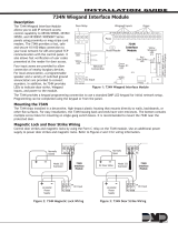
MAC : 00:01:22:33:44:55
MOD : DUALCOM
VER : 194 122319
SN : 0012345A CODE21852
TD : 011520
KEY : 100
Example Default
Master Code

Digital Monitoring Products XR150INT/XR550INT Series Programming Guide
2
PROGRAMMER OPERATION
There are 20 programming sections to choose from:
Programming Item Section in This Manual Programming Item Section in This Manual
Initialization 2 Output Information 12
Communication 3 Output Groups 13
Network Options 4 Menu Display 14
Device Setup 6 PC Log Reports 16
Remote Options 7 Area Information 17
System Reports 8 Zone Information 18
System Options 9 Stop 19
Bell Options 10 Set Lockout Code 20
Output Options 11 Feature Upgrade 21
To choose a section for programming, press any select key or area when the keypad displays the name of that section.
Sections 2 through 21 contain detailed instructions for each programming step.
PROGRAMMER LOCKOUT CODES
The panel allows you to enter the programming function without entering a lockout code using steps 1 to 4 listed in
Getting Started. We recommend, however, that you install a Lockout Code to restrict programming to only those persons
your company authorizes. You can do this by using the SET LOCKOUT CODE feature in the Programmer. The Lockout
Code restricts any unauthorized panel programming.
After resetting the panel and entering the code 6653, the keypad displays PROGRAMMER. Press CMD to advance
through the programming sections until SET LOCKOUT CODE displays (after STOP). Press any select key or area. The
keypad displays ENTER CODE: – . Enter a 3 to 5 digit Programmer Lockout Code and press CMD. The keypad displays
ENTER AGAIN followed by ENTER CODE: –. Enter the same 3 to 5 digit code a second time and press CMD. The keypad
displays CODE CHANGED. The panel does not accept a 5-digit Lockout Code higher than 65535.
Before accessing programmer functions enter the new code number. Write the Lockout Code number down and keep it
in a secure place with access limited to authorized persons only. Lost Lockout Codes require the panel to be sent back to
DMP for repair. You may cancel a Lockout Code by entering 00000 at the Set Lockout Code command.
RESET TIMEOUT
The panel has a feature that requires you to enter the Programmer within 30 minutes of resetting the panel. After 30
minutes, if you attempt to program by entering the 6653 (PROG) code, the keypad displays: RESET PANEL. You must
reset the panel and enter the program code then begin programming within the next 30 minutes.
If you are already in the Programmer and do not press any keys on the programming keypad for 30 minutes, the panel
terminates programming. All data entered up to that time is not saved unless you run the Stop routine.
Use the Stop routine to exit panel Programming. Ensure the keypad displays “SAVING PROGRAM” to save all
programming changes entered.
POWER UP
When the panel is powered up after an AC power failure, any zone transitions are not recognized for 60 seconds. Normal
zone processing resumes at the end of the 60 seconds.
KEYPADS
DMP oers multiple keypads in a variety of styles that provide programming capabilities.
SPECIAL KEYS
The following special keys/areas are common to all DMP keypads.

XR150INT/XR550INT Series Programming Guide Digital Monitoring Products
3
COMMAND (CMD) Key
Pressing CMD allows you to go forward through the programming menu and through each step of a programming sec-
tion. As you go through the programming, the keypad display shows any current programming already stored in the
panel memory. If no change is required for an option, press CMD to advance to the next step.
CMD is also used to enter information into the panel’s memory such as phone numbers or zone names. Press CMD after
entering information.
Back Arrow (<—) Key
Use the Back Arrow key to back up one step while programming. The Back Arrow key is also used when an error is made
while entering in formation. Press the Back Arrow key once to erase the last character entered.
Select Keys or Areas
The top row of keys are called the select keys on Thinline and Aqualite keypads or select areas on Graphic Touchscreen
keypads. Each time you need to press a select key or area, the keypad displays the function or options above one of the
keys or in the select area. Displaying choices above individual select keys or in select areas allows them to be used for
many dierent applications. For example, you can enter AM or PM when programming the automatic test time or answer
YES or NO for a system option.
During programming, the select keys or areas also allow you to change infor mation currently in panel memory by
pressing the appropriate select key or area under or on the display. You then enter the new information using the keypad
data entry digit keys.
When there are more than four re sponse options avail able, press CMD to display the remaining options. Pressing the
Back Arrow key allows you to review the previous four choices.
The select keys or areas are also used for choosing a section from the pro gramming menu. Press any select key or touch
the select area when the programming section name you want displays.
On Wireless, Thinline and Aqualite keypads, when instructed to press the first select key, press the far left select key; the
second select key is the second from the left; third select key is second from the right; and the fourth select key is the far
right key.
On Graphic Touchscreen Keypads, when instructed to press the first select key, touch select area 1; the second select key
touch select area 2; third select key touch select area 3; and the fourth select key touch select area 4.
ENTERING ALPHA CHARACTERS
Some options during programming require you to enter alpha characters. To enter an alpha character, press or touch
the key that has that letter written below it. The keypad displays the number digit of the key. Next, press the select key
or area that corresponds to the location of the letter under the key. Pressing a dierent select key or area changes the
letter. When another digit key is pressed, the last letter displayed is retained and the process starts over.
ENTERING NON-ALPHA CHARACTERS
To enter a space in an alpha entry, press the 9 digit key followed by the third select key or area. The three characters on
the 9 digit key are Y, Z, and space. You can also enter the following characters: – (dash), . (period), * (asterisk), and #
(pound sign) using the 0 (zero) key and the four select key or area from left to right. For example, to enter a – (dash),
press the 0 (zero) key and then the left select key or area. A dash now appears in the keypad display. The table below
shows the character locations for DMP keypads.

Digital Monitoring Products XR150INT/XR550INT Series Programming Guide
4
Key Number Select Key or
Area 1
Select Key or
Area 2
Select Key
or Area 3
Select Key or
Area 4
1 A B C (
2 D E F )
3 G H I !
4 J K L ?
5 M N O /
6 P QR &
7 S T U @
8 V W X ,
9 Y Z space _
0 - . * #
KEYPAD DISPLAYS CURRENT PROGRAMMING
Each programming option displayed at the keypad shows the currently selected option in the panel memory. These
options are either shown as a number, a blank, or a NO or YES. To change a number or blank to a new number, press any
select key or touch any select area. The current option is replaced with a dash.
Press the number(s) on the keypad you want to enter as the new number for that option. It is not necessary to enter
numbers with leading zeros. The panel automatically right justifies the number when you press CMD.
To change a programming option that requires a NO or YES response, press the select key or touch the select area for
the response not selected.
For example, if the current option is selected as YES and you want to change it to NO, on Thinline or Aqualite keypads
press the third select key. On Graphic Touchscreen keypads touch select area 3. The display changes to NO. Press CMD
to display the next option.
MULTIPLE DISPLAYS
For many programming and user options, such as Area selections, Menu Displays, and Status Lists, there are several
displays containing programming. For example, when programming Menu Displays, keypads 1 through 16 display on two
separate displays. First, keypads 1 through 8 display. Press CMD to display keypads 9 through 16. This same scheme is
used for areas 1 through 32. Areas not pre-programmed at installation to display at this keypad cannot be viewed.
ASTERISKS IN PROGRAMMING
Asterisks display next to a programming option that is already selected. As shown in the example, options that are
selected to display the current programming selection have an asterisk next to the number. Those that are not selected
simply display the number. In the Devices example, keypads 3, 8, 9, and 15 are not selected. In the Areas example, areas
3, 8, 9, 15, 19, 23, 25, and 31 are not selected. In both examples the numbers with asterisks are selected.
To select or deselect a number, simply enter the number using the digit keys on the keypad. This same scheme is used
when viewing the panel armed status and other programming and operational functions. Remember to press CMD to
display the rest of the device or area numbers.
COMPLIANCE INSTRUCTIONS
This product incorporates field-programmable software. Refer to the XR150INT/XR550INT Compliance Listing Guide
(LT-1330INT) for additional compliance information.

XR150INT/XR550INT Series Programming Guide Digital Monitoring Products
5
INITIALIZATION
Initialization
This function allows you to clear selected parts of the panel program back to the factory
defaults.
Clear All Memory
NO leaves existing programming intact then displays Clear All Codes.
YES clears all memory then displays Reset Panel. Reset the panel by shorting the reset
jumper and re-enter programming mode to continue.
Clear All Codes
NO leaves existing codes intact.
YES clears the user code and user profile memory and assigns user code number 99 to the
highest user number.
Clear All Schedules
NO leaves existing schedules intact.
YES clears all shift and output schedules.
Clear Display Events Memory
NO leaves existing event memory intact.
YES clears the events memory.
Clear Zone Information
NO leaves existing zone information intact.
YES clears the zone information for all zones.
Clear Area Information
NO leaves existing area information intact.
YES clears the area information for all areas.
Clear Output Information
NO leaves existing output information intact.
YES clears all programmed output names and any output cuto assignment.
Clear Communication and Remote Options
NO leaves existing communication and remote options intact.
YES reset communication and remote options programming to factory defaults.
Clear Wi-Fi
NO leaves existing Wi-Fi programming intact.
YES reset Wi-Fi programming to factory defaults.
Set to Factory Defaults
NO leaves existing panel programming intact.
YES sets the panel’s programming back to factory default selections and clears all
Favorites, Device Setup, System Options, and Remote Options programming from the
panel. Selecting YES does not clear the panel’s event memory, zone, user code information,
or schedules.
INITIALIZATION
INIT ALL? NO YES
CODES? NO YES
SCHEDS? NO YES
EVENTS? NO YES
ZONES? NO YES
AREAS? NO YES
OUTPUTS? NO YES
COM/RMT? NO YES
WIFI? NO YES
DEFAULTS NO YES

Digital Monitoring Products XR150INT/XR550INT Series Programming Guide
6
COMMUNICATION
Communication
Configure the communication options for the panel. The information you program varies
with the Communication Type you select.
Account Number
The Account Number is a 1 to 5 digit number used to identify which panel is sending a
message. Enter the account number sent to the SCS-1R Receiver. The default is 12345.
The range of valid account numbers for a panel is 1 to 65535. For accounts of four digits or
less, do not enter leading zeros.
Transmit Delay
Enter the number of seconds (15 to 45) the panel waits before sending burglary zone
(Night, Day, or Exit) reports to the receiver. Other zone type reports are sent immediately.
Alarm bells and relay outputs are not delayed during this period. Program Burglary
Outputs for pulsed or steady, and set Abort Reports to YES if Opening and Closing reports
are not being sent. Enter 0 (zero) to disable this function. The default is 30.
If the area where the alarm occurred is disarmed during the Transmit Delay time, only an
Abort Report (S45) message is sent to the receiver. If the area where the alarm occurred
is disarmed after the alarm message is sent to the receiver but before the Bell Cuto
time expires even if the alarm was silenced, an Alarm Cancelled (S49) message is sent.
Otherwise the alarm is sent at the end of the delay.
Communication Path
Up to eight communication paths may be programmed. Each path is designated as a
primary or backup communication route. Path 1 is always Primary but other paths may be
programmed as additional primary or backup.
Each primary path establishes a new path group. A path group is made up of the primary
path and its subsequent backup paths. Typical communication takes place on the primary
path with backup paths being used only when the primary path fails or when the backup
path is programmed to duplicate messages. There is no option to backup path 8.
Communication Type
Specifies the communication method the panel uses on this path to report system events
to DMP SCS-1R or SCS-VR Receivers. Default is NONE for Path 1-8.
NONE - For local systems. Selecting NONE ends communication programming.
DD - Digital Dialer communications to a DMP SCS-1R Receiver.
NET - Network communication using the panel onboard network connection. The DMP
Network/Output reporting format is transmitted over a data network to the SCS-1R or SCS-
VR Receiver.
CID - This option allows the panel to communicate to DMP and non-DMP receivers using
the Contact ID format.
CELL - This option allows communication over the cellular network using the 263C or 263H
Cellular Communicator.
WIFI - Network communication to DMP Model SCS-1R or SCS-VR Receivers.
Path Type
The Path Type defines if the path is Primary or Backup. Because Path 1 is Primary, this
option only displays for paths 2-8. Default is BACKUP.
If the Primary Communication Type is CELL, then the backup Communication Type can
only be NET.
Test Report
Test Report determines if test reports (Automatic Recall Test OK or Unrestored System) are
sent on this path. Reports are sent according to the programming in Test Frequency and
Test Time. Default is YES.
Select YES to allow the programmed test report to be sent on the path currently being
programmed.
COMMUNICATION
ACCOUNT NO: 12345
XMIT DELAY: 30
PATH: -
COMM TYPE: NONE
NONE DD NET CID
CELL WIFI
PATH TYPE: BACKUP
PRIMARY BACKUP
TEST RPT: YES
NO YES DEFER

XR150INT/XR550INT Series Programming Guide Digital Monitoring Products
7
Select DEFER to not send a test report if the panel communicates any message to the
receiver within the time set in Test Frequency.
Select NO to not send test reports on this path.
Test Frequency
Test Frequency determines the frequency of the test report. Enter a number from 1 to 60
and select DY (Day) or HR (Hour) by pressing the far right select key or area. Default is 1
Day.
Test Day
Use this option to set the day of the Test Report. This option appears only when Test Report
is Yes, Test Frequency is Day and a multiple of seven. Press CMD to display the first four
days of the week. Press CMD to display the last three days. Select the day of the week to
send the test report. Default is SUNDAY.
Test Time
Use this option to select the time of day for Test Reports. Select the hour, minute and AM/
PM. Enter 0:00 AM to disable this feature. Default is 0:00 AM.
Check In
This option displays if the COMM TYPE is NET, WIFI, or CELL. Check-in reports are a
method of supervising the panel for communication with the receiver. For NET the default
is YES. For CELL the default is YES.
Select RND (Random) for the panel to check-in at random times from 6 to 60 minutes when
all areas are disarmed. If any area is armed a check-in is sent every 6 minutes.
Select ADPT (Adaptive) for a backup path to adapt to the check-in programming from
this groups primary path if the primary path becomes unavailable. Check-in programming
includes Check-in and Fail Time.
Select ADP3 (Adaptive 3) for a backup path to adapt using a 3 minute Check-in and Fail
Time if the primary path becomes unavailable. This option also indicates a Communication
Trouble (S10) if the cell tower is unavailable for 3 minutes.
When YES is selected, enter the number of minutes between check-in reports, from 2 to
240 for NET or 3 to 240 for CELL, when the panel is armed or disarmed. For CELL the
default is 0. For NET the default is 200.
Fail Time
This option displays if CHECKIN is set to YES. Entering a FAIL TIME allows the receiver to
miss multiple check-ins before logging that the panel is missing. The maximum fail time is
240 minutes. For example, if CHECKIN is 10 and FAIL TIME is 30, the receiver only indicates
a Panel Not Responding after 30 minutes. The FAIL TIME must be equal to or greater than
the CHECKIN time. Default is equal to CHECKIN for CELL. Default is 240 for NET.
Encryption (XR550INT with Encryption Only)
This option displays if the Communication Type is NET or CELL. Select 128 or 256 to enable the
encryption level for the path currently being programmed. Default is NO.
256-bit encrypted messages to the SCS-1R receiver only communicate when using SCS-104
Receiver Line Cards with Version 102 or higher software.
IPV6 Address
This prompt determines if the network path uses IPV6 for communication. Default is NO.
TEST FREQ: 1 DY
TEST DAY: SUN
TEST TIME:
0:00 AM
TEST DAY: SUN
CHECKIN
NO YES RND ADPT
CHECKIN
ADP3
CHECKIN MINS: 200
FAIL MINS: 240
ENCRYPT: NO
NO 128 256
USE IPV6:
NO YES

Digital Monitoring Products XR150INT/XR550INT Series Programming Guide
8
Receiver IP
This option displays if the Communication Type is NET or CELL. Enter the Receiver IP
address where the panel sends network messages. The Receiver IP Address must be
unique and cannot be duplicated on the network. Enter all 12 digits and leave out the
periods. For example, enter IP address 192.168.0.250 as 192168000250. The periods
display automatically. If IPV6 is selected the receiver IP will need to be an IPV6 address. If
changing from IPV6 YES to IPV6 NO, you will need to modify their IP address to IPV4.
Receiver Port
Enter the receiver port number. Valid range is 1 to 65,535. Default is 2001.
First Telephone Number
This option displays only if the Communication Type is DD or CID.
This is the first number the panel dials when sending reports to the receiver. Phone
numbers can have two lines of 16 characters each to equal up to 32 characters.
Second Telephone Number
The panel dials the second number when two successive tries using the first number fail. If
the panel cannot reach the receiver after two attempts using the second number, it returns
to the first number and makes two additional attempts. A total of ten dialing attempts are
made using the first and second phone num bers.
Advanced Programming
Select YES to enter the Advanced Programming menu for the communication
path currently being programmed. Selecting NO ends programming of the current
communication path and takes users back to the Communication Path option to program a
secondary path.
APN
Enter the first APN (Access Point Name). This allows an access point for cellular
communication and is used to connect to a DNS network. The APN may contain two lines
of 16 characters to equal 32 characters. Default is set to SECURECOM400.
Fail Test Hours
This option sets the frequency for a Backup or Adaptive path to send a test report when
the closest previous path fails within its path group.
If Fail Test Frequency is set to 0, test reports are sent only according to Test Report
programming. Range is 0 to 24 hours. Default is 0.
Protocol
This option displays only if Communication Type is NET.
Select TCP to communicate over the network using TCP protocol. Select UDP to
communicate using UDP protocol. Default is TCP.
Retry Seconds
This option displays only when Communication type is NET.
Enter the number of seconds (between 6 and 15) the panel should wait before retrying to
send a message to the receiver if an acknowledgment was not received. The panel retries
as many times as possible for a period of one minute before sending a network trouble
message. The default Retry Time is 6 seconds.
RECEIVER IP
000.000.000
RECEIVER PORT
2001
FIRST PHONE NO:
SECOND PHONE NO:
ADVANCED? NO YES
APN
SECURECOM400
FAIL TEST HRS: 0
PROTOCOL: TCP
RETRY SECONDS: 6

XR150INT/XR550INT Series Programming Guide Digital Monitoring Products
9
Substitution Code
This option displays when the Communication Type is NET or CELL. The Panel Substitution
Code increases the level of security by helping to ensure that the panel sending the
message to the receiver has not been substituted by another panel. The default is NO.
Select YES to send a substitution code with every message.
Select SHARED (SHR) to use the same substitution code that was used in the previous
path.
893A
This option displays when the Communication Type is DD or CID.
The 893A option allows reports to be sent to the receiver on a second DD line using the
893A module. Default is NO.
When using an 893A, Test Report messages (S07 Automatic Recall Test or S88
Unrestored System Recall Test) are sent to the receiver at the frequency programmed in
Test Frequency, alternating between the first and second phone line.
Alarm Switch
This option displays only if using the DD or CID Communication Types.
Enter the number of attempts to send an alarm message before switching to the next path.
Range is from 1 to 10. All non-alarm messages are sent for 10 attempts on the dialer before
a switch is initiated. If the path immediately following this channel is not a backup path, this
option has no eect. Default is 1.
Duplicate Alarms
This option displays for BACKUP paths. If Yes is selected, the current backup path
duplicates all alarms occurring on its group primary path. Default is NO.
Alarm Reports
This option displays when the Path Type is Primary. All backup paths within the group
follow the same programming for Alarm Reports. Default is YES.
When YES is selected, the following reports are sent to the receiver for all zone types:
• Alarm • Bypass • Reset • Restore
When FIRE is selected, the following reports are sent for Fire, Fire Verify and Supervisory
Zones:
• Alarm • Bypass • Reset • Restore
Supervisory/Trouble Reports
This option displays when the Path Type is Primary. All backup paths within the group
follow the same programming for Supervisory/Trouble Reports. Default is YES.
When YES is selected, the following reports are sent for all zone types:
• Trouble • Low Battery • Missing • Fault
• Restorals • System Troubles • System Restoral
When FIRE is selected, the following reports are sent for Fire, Fire Verify, and Supervisory
Zones:
• Trouble • Low Battery • Missing • Fault
• Restorals • System Troubles • System Restoral
Serviceman reports are sent regardless of the selection made for Supervisory/Trouble
reports.
SUB CODE: NO
NO YES SHARED
893A: NO YES
ALARM SWITCH: 1
DUPLICATE ALARMS
NO YES
ALARM YES
NO YES FIRE
SPV/TRBL YES
NO YES FIRE

Digital Monitoring Products XR150INT/XR550INT Series Programming Guide
10
Opening/Closing and User Reports
This option displays when the Path Type is Primary. All backup paths within the group
follow the same programming for Opening/Closing and User Reports. Default is YES.
When YES is selected, the following reports by user are sent to this receiver.
• Opening • Code changes (including adding, deleting, changing)
• Closing • Schedule changes (temporary, permanent, shift)
• Bypass • Holiday date changes
• Reset
Door Access Report
This option displays when the Path Type is Primary. All backup paths within the group
follow the same programming for Door Access Reports. Default is DENY.
Select YES to enable Door Access Granted and Denied reports to this receiver whenever
a door access is granted to a user. The Door Access Granted report is only sent if the
keypad number has also been selected in Access Keypads under the SYSTEM REPORTS
programming.
Select DENY to enable Door Access Denied reports only to this receiver when a door
access is denied to a user.
Panic Test (Network Only)
YES allows the panic zone test verification and failure results to be sent to the central
station receiver. NO disables the panic test report. The default setting is NO. The system
test start, stop, panic zone verification, and panic zone failure messages sent to the central
station and the trips count operation are the same as used under the Walk Test. See Using
the Walk Test section in the Appendix.
Send Communication Trouble
This option displays for each path and determines if and how communication trouble on
the path is sent to the receiver. A trouble message indicates both the path number and
communication type that failed. Default is YES.
Send Path Information
This option displays for each path and if YES, each panel message includes path
information such as path number, communication type, and path type. Default is NO.
O/C USER NO YES
DOOR ACS DENY
NO YES DENY
PANIC TST NO YES
SEND COMM TRBL:
NO YES
SEND PATH INFO:
NO YES

XR150INT/XR550INT Series Programming Guide Digital Monitoring Products
11
NETWORK OPTIONS
Network Options are provided to define the network configuration for the panel. This information will be used during
communication of messages via network. A 763 Wi-Fi Module is required in order to send alarm signal communication.
IP addresses and port numbers may need to be assigned by the network administrator. When entering an IP, Gateway, or
Subnet Mask address be sure to enter all 12 digits and leave out the periods.
Wi-Fi Setup
This option is for connecting to the desired Wi-Fi network and will display only when
Comm Type is set to Wi-Fi. Press any select key or area to select.
WPS - Automatically connects to a WPS enabled router.
LIST - Displays the names and signal strength of any Wi-Fi routers in range.
MANUAL - Enter the name of the Wi-Fi router you wish to connect to.
TEST - Verifies connection of your system to the Wi-Fi network.
WPS
When WPS is selected, SEARCHING displays. Press the WPS button on the Wi-Fi network
router to which you are attempting to connect. SEARCHING displays for up to two minutes
or until connected to the WPS enabled router. Refer to the router’s instruction manual for
sending a security key to the XR150INT/XR550INT Series panel.
If the panel fails to connect to the WPS enabled router, WPS FAILED RETRY? NO YES
displays. Press the fourth select key or area to RETRY or press the third select key or area
to display WPS LIST MANUAL.
List
When LIST is selected, SEARCHING displays until any Wi-Fi networks are found in range.
Once available Wi-Fi networks are found the keypad displays the name of the SSID (Wi-Fi
Network name) and signal strength of each network. Press CMD to scroll through the list
of available Wi-Fi networks. When the desired network is displayed, press any select key or
area to connect.
Manual
This option allows you to enter the desired network name using the keypad. When
MANUAL is selected, the current settings display. Press CMD to continue with no change.
SecureCom is the default.
Once the SSID is entered, press CMD and SEARCHING displays.
When an SSID is entered for the first time or changed, the panel searches for the SSID
entered to ensure communication. The keypad displays SSID FOUND or SSID NOT FOUND.
When the SSID is found, the security type is also detected.
Enter up to 32 characters for the SSID from the network router to identify the network LAN.
The SSID is blank by default. Use the chart below to enter lowercase or special characters.
Each successive press of the select key or area gives additional options.
Key Number Select Key
or area 1
Select Key
or area 2
Select Key
or area 3
Select Key
or area 4
1 A, a, B, b C, c (, [, {
2D, d E, e F, f ), ], }
3 G, g H, h I, i !, ^, ~
4J, j K, k L, l ?, ", |
5 M, m N, n O, o /, \, `
6P, p Q, q R, r &, $
7 S, s T, t U, u @, %
8V, v W, w X, x , =
9Y, y Z, z space, : _, ;
0 -, + ., ' *, < #, >
If the 763 is unable to connect to the desired network and SSID NOT FOUND displays,
press CMD to return to the main menu and WPS LIST MANUAL displays. Press CMD again
to display TEST.
WPS LIST MANUAL
TEST
WPS LIST MANUAL
TEST
SEARCHING
WPS LIST MANUAL
SEARCHING
SIGNAL XXXXXX
HOMENET123
WPS LIST MANUAL
WIFI SETUP
ENTER SSID
SSID
SSID FOUND
SSID
SSID NOT FOUND

Digital Monitoring Products XR150INT/XR550INT Series Programming Guide
12
Test
Press the first select key or area to select TEST and the 763 Wi-Fi module will attempt to
verify connection of your system to the selected Wi-Fi network.
Wireless Security Type
When successful, W/L SECURITY displays. Select the security type based on the network
router programming. The default network security type is WPA-PSK. Press any select key
or area to display the other security options. The available options are WEP, WPA, and
NONE.
Press the first select key or area to choose WEP, press the second select key or area for
WPA, press the third select key or area for NONE.
Wireless Network Key
This option displays only if Comm Type is set to Wi-Fi and Security option is not set to
NONE. Enter the key provided from the network router’s programming. WEP requires
a network password of 10 characters (WEP64) or 26 characters (WEP128), using a
combination of the number 0-9 and the letters A-F (See the chart above to enter
lowercase or special characters).
WPA/WPA-PSK uses a custom key that allows 8 to 32 characters.
When connecting to the Wi-Fi network the panel also detects the security type in use and
W/L KEY: *************** displays.
Enter the W/L KEY and the panel performs a connection test and CONNECTING displays.
When successful, CONNECTED displays on the keypad. If the panel does not connect to
the Wi-Fi network, NOT CONNECTED displays. Press CMD to return to the Wi-Fi SETUP
main screen.
Depending on the security type, the key might take several seconds to process.
IPV6
At the IPV6 prompt, select YES to use an IPV6 address. The default is NO. IPV6 is DHCP
only.
DHCP
If the panel uses a dynamic IP address select YES. When set to YES, the panel operates
using DHCP and does not use the Local IP Address number. When the DHCP option is set
to NO, the panel uses the IP address entered in Local IP Address. The default value for
DHCP mode is YES.
Local IP Address
Enter the local IP address for the panel. The Local IP Address must be unique and cannot
be duplicated. The default local IP address is 192.168.0.250.
Gateway Address
Enter the local gateway address. The Gateway IP Address is needed to exit your local
network. The default gateway address is 192.168.0.1.
Subnet Mask
Enter the local subnet mask assigned to the panel. The default subnet mask address is
255.255.255.000.
DNS Server
Enter the IP address of the DNS (Domain Name System) used by the panel to resolve
domain names into IP addresses. The default address is 192.168.0.1.
On systems with hardwired network connection, the DNS address can be changed even if
the panel has DHCP enabled.
TEST
W/L SECURITY
WPA-PSK
W/L SECURITY
WEP WPA NONE
W/L KEY
*****************
USE IPV6:
NO YES
DHCP NO YES
LOCAL IP ADDRESS
192 .168.1.19
GATEWAY ADDRESS
192 .168.1.1
SUBNET MASK
255.255.255.000
DNS SERVER
192.168.0.1
/