Page is loading ...

Instructions
1336 PLUS II Fan Replacement
Frames B & C
This publication will guide you through fan replacement on Frames B & C
of the 1336
PLUS II AC Drive.
Kit Contents
• Fan with leads
• Connector with leads
• Sealant
• Splice (2)
• Grommet
Fan Replacement
1. Remove and lock-out all incoming power to the drive. Remove/open the
drive cover.
2. Using figure 1, locate the fan and attached wires. Note wire routing.
3. Remove the fan connector from the chassis. Cut the wire approximately
25.4 mm (1 in.) from the connector. Discard wire and connector.
4. Remove the four screws securing the fan guard to the heatsink. Set the
fan guard and screws aside. Remove and discard the fan and wires.
5. Install the supplied grommet in the opening for the fan wires.
6. Locate the replacement fan. Route the fan wires as noted earlier. Using
the screws previously removed, secure the fan and fan guard.
Important: Verify that the air flow arrow on the fan points to the top of
the drive.
!
ATTENTION: This drive contains ESD (Electrostatic
Discharge) sensitive parts and assemblies. Static control
precautions are required when installing, testing, servicing
or repairing this assembly. Component damage may result
if ESD control procedures are not followed. If you are not
familiar with static control procedures, reference A-B
publication 8000-4.5.2, “Guarding Against Electrostatic
Damage” or any other applicable ESD protection
handbook.
!
ATTENTION: To avoid a shock hazard, assure that all
power to the drive has been removed before proceeding. In
addition, verify that the DC bus has discharged by
measuring across the “+DC” and “–DC” terminals of TB1
with a voltmeter. The voltage should be 0.0VDC.

2 1336 PLUS II Fan Replacement Frames B & C
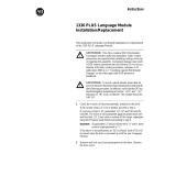
Figure 1 Fan Location
7. Using the supplied splice, join the fan leads together as follows:
a. Insert red wires in splice cover, overlapping ends slightly.
b. Close cover (keeping wires in position) and squeeze with pliers until
cover is locked.
c. Repeat for black wires.
8. Install fan connector. Apply supplied sealant to wires at the chassis hole.
9. Apply drive power and verify fan operation. Ensure that air is moving
towards the top of the drive.
Connector
Fan Leads
Fan
to Fan
Publication 1336F-IN012A-EN-P – October, 2003 P/N 320675-P01
Copyright © 2003 Rockwell Automation. All rights reserved. Printed in USA.
/