Page is loading ...

CONFORMANCE TESTED
TM
User Manual
DeviceNet™
Communications
Module
Catalog Number 1203-GK5 or 1336-GM5
Firmware 1.xxx-3.xxx
efesotomasyon.com - Allen Bradley,Rockwell,plc,servo,drive

Important User Information
Solid state equipment has operational characteristics differing from those of
electromechanical equipment. “Safety Guidelines for the Application,
Installation and Maintenance of Solid State Controls” (Publication SGI-1.1
available from your local Allen-Bradley Sales Office or online at http://
www.ab.com/manuals/gi) describes some important differences between
solid state equipment and hard-wired electromechanical devices. Because of
this difference, and also because of the wide variety of uses for solid state
equipment, all persons responsible for applying this equipment must satisfy
themselves that each intended application of this equipment is acceptable.
In no event will the Allen-Bradley Company be responsible or liable for
indirect or consequential damages resulting from the use or application of
this equipment.
The examples and diagrams in this manual are included solely for
illustrative purposes. Because of the many variables and requirements
associated with any particular installation, the Allen-Bradley Company
cannot assume responsibility or liability for actual use based on the
examples and diagrams.
No patent liability is assumed by Allen-Bradley Company with respect to
use of information, circuits, equipment, or software described in this
manual.
Reproduction of the contents of this manual, in whole or in part, without
written permission of the Allen-Bradley Company is prohibited.
Throughout this manual we use notes to make you aware of safety
considerations.
Attentions help you:
• identify a hazard
• avoid the hazard
• recognize the consequences
Important: Identifies information that is especially important for successful
application and understanding of the product.
!
ATTENTION: Identifies information about practices or
circumstances that can lead to personal injury or death, property
damage, or economic loss.
Shock Hazard labels may be located on or inside the drive to
alert people that dangerous voltage may be present.
efesotomasyon.com - Allen Bradley,Rockwell,plc,servo,drive

Summary of Changes
Summary of Changes
The information below summarizes the changes made to the manual
since the last release. These changes are a result of the 3.xxx firmware
upgrade.
DeviceNet Communications Modules with firmware 3.xxx support an
internal (Rockwell use only) Object for use with IntelliCENTER™
software. This firmware update is transparent to the user.
efesotomasyon.com - Allen Bradley,Rockwell,plc,servo,drive

soc–2 Summary of Changes
Notes
efesotomasyon.com - Allen Bradley,Rockwell,plc,servo,drive

Table of Contents
Preface
Using this Manual Objectives . . . . . . . . . . . . . . . . . . . . . . . . . . . . . . . . . . . . . . . . . . . . . . . . . P-1
Who Should Use this Manual? . . . . . . . . . . . . . . . . . . . . . . . . . . . . . . . . . P-1
Purpose of this Manual . . . . . . . . . . . . . . . . . . . . . . . . . . . . . . . . . . . . . . . P-1
Safety Precautions. . . . . . . . . . . . . . . . . . . . . . . . . . . . . . . . . . . . . . . . . . . P-3
Terms and Abbreviations . . . . . . . . . . . . . . . . . . . . . . . . . . . . . . . . . . . . . . P-3
Conventions Used in this Manual . . . . . . . . . . . . . . . . . . . . . . . . . . . . . . . P-4
Rockwell Automation Support . . . . . . . . . . . . . . . . . . . . . . . . . . . . . . . . . . P-4
Chapter 1
Overview Chapter Objectives . . . . . . . . . . . . . . . . . . . . . . . . . . . . . . . . . . . . . . . . . . 1-1
Overview of the 1203-GK5 Module and 1336-GM5 Board . . . . . . . . . . . . 1-1
Features of the 1203-GK5 Module and 1336-GM5 Board . . . . . . . . . . . . . 1-2
SCANport Products . . . . . . . . . . . . . . . . . . . . . . . . . . . . . . . . . . . . . . . . . . 1-3
Hardware and Parts Description . . . . . . . . . . . . . . . . . . . . . . . . . . . . . . . . 1-4
Overview of Setting Up the 1203-GK5 Module or 1336-GM5 Board . . . . . 1-5
Required Tools and Equipment . . . . . . . . . . . . . . . . . . . . . . . . . . . . . . . . . 1-6
Chapter 2
Configuring the 1203-GK5 Module
or 1336-GM5 Board
Chapter Objectives . . . . . . . . . . . . . . . . . . . . . . . . . . . . . . . . . . . . . . . . . . 2-1
Factory-Default Settings . . . . . . . . . . . . . . . . . . . . . . . . . . . . . . . . . . . . . . 2-1
Locating the DIP Switches. . . . . . . . . . . . . . . . . . . . . . . . . . . . . . . . . . . . . 2-1
Configuring the 1203-GK5 Module or 1336-GM5 Board . . . . . . . . . . . . . . 2-2
Chapter 3
Installing the 1203-GK5 Module or
1336-GM5 Board
Chapter Objectives . . . . . . . . . . . . . . . . . . . . . . . . . . . . . . . . . . . . . . . . . . 3-1
Selecting Cables . . . . . . . . . . . . . . . . . . . . . . . . . . . . . . . . . . . . . . . . . . . . 3-1
Installing a 1203-GK5 Module . . . . . . . . . . . . . . . . . . . . . . . . . . . . . . . . . . 3-3
Removing the 1203-GK5 Communications Module. . . . . . . . . . . . . . . . . . 3-6
Installing a 1336-GM5 Board . . . . . . . . . . . . . . . . . . . . . . . . . . . . . . . . . . . 3-7
Removing the 1336-GM5 Communications Board . . . . . . . . . . . . . . . . . 3-10
Chapter 4
Configuring a Scanner to
Communicate with the 1203-GK5
Module or 1336-GM5 Board
Chapter Objectives . . . . . . . . . . . . . . . . . . . . . . . . . . . . . . . . . . . . . . . . . . 4-1
About DeviceNet Manager. . . . . . . . . . . . . . . . . . . . . . . . . . . . . . . . . . . . . 4-1
About RSNetWorx for DeviceNet . . . . . . . . . . . . . . . . . . . . . . . . . . . . . . . . 4-1
Required Equipment and Software . . . . . . . . . . . . . . . . . . . . . . . . . . . . . . 4-1
Getting Started. . . . . . . . . . . . . . . . . . . . . . . . . . . . . . . . . . . . . . . . . . . . . . 4-2
Using Online Mode in DeviceNet Manager . . . . . . . . . . . . . . . . . . . . . . . . 4-2
Creating an EDS File for the Adapter and Product . . . . . . . . . . . . . . . . . . 4-4
Configuring a PLC Scanner (1771-SDN) to Communicate with a 1203-GK5
Module or 1336-GM5 Board . . . . . . . . . . . . . . . . . . . . . . . . . . . . . . . . . 4-8
Configuring an SLC Scanner (1747-SDN) to Communicate with a 1203-GK5
Module or 1336-GM5 Board . . . . . . . . . . . . . . . . . . . . . . . . . . . . . . . . 4-13
Saving a Configuration to a File and Quitting DeviceNet Manager . . . . . 4-18
Viewing and Editing Parameters . . . . . . . . . . . . . . . . . . . . . . . . . . . . . . . 4-20
efesotomasyon.com - Allen Bradley,Rockwell,plc,servo,drive

toc–ii Table of Contents
Chapter 5
Creating a Ladder Logic
Program
Chapter Objectives. . . . . . . . . . . . . . . . . . . . . . . . . . . . . . . . . . . . . . . . . . . 5-1
Required Equipment . . . . . . . . . . . . . . . . . . . . . . . . . . . . . . . . . . . . . . . . . 5-1
About RSLogix . . . . . . . . . . . . . . . . . . . . . . . . . . . . . . . . . . . . . . . . . . . . . . 5-1
About Ladder Logic Programs . . . . . . . . . . . . . . . . . . . . . . . . . . . . . . . . . . 5-2
Example Ladder Logic Programs. . . . . . . . . . . . . . . . . . . . . . . . . . . . . . . . 5-2
Chapter 6
Using DeviceNet Explicit
Messages
Chapter Objectives. . . . . . . . . . . . . . . . . . . . . . . . . . . . . . . . . . . . . . . . . . . 6-1
Required Equipment . . . . . . . . . . . . . . . . . . . . . . . . . . . . . . . . . . . . . . . . . 6-1
Message Translations . . . . . . . . . . . . . . . . . . . . . . . . . . . . . . . . . . . . . . . . 6-1
Messaging for the 1771-SDN Scanner. . . . . . . . . . . . . . . . . . . . . . . . . . . . 6-2
Messaging for the 1747-SDN Scanner. . . . . . . . . . . . . . . . . . . . . . . . . . . . 6-4
Examples . . . . . . . . . . . . . . . . . . . . . . . . . . . . . . . . . . . . . . . . . . . . . . . . . . 6-6
Using Messages to Control SCANport Products . . . . . . . . . . . . . . . . . . . 6-11
Writing to Register Objects . . . . . . . . . . . . . . . . . . . . . . . . . . . . . . . . . . . 6-12
Chapter 7
Troubleshooting Chapter Objectives. . . . . . . . . . . . . . . . . . . . . . . . . . . . . . . . . . . . . . . . . . . 7-1
LEDs on the DeviceNet Adapter . . . . . . . . . . . . . . . . . . . . . . . . . . . . . . . . 7-1
DeviceNet Network Status LED . . . . . . . . . . . . . . . . . . . . . . . . . . . . . . . . . 7-2
SCANport Status LED States . . . . . . . . . . . . . . . . . . . . . . . . . . . . . . . . . . 7-3
Appendix A
Specifications Appendix Objectives. . . . . . . . . . . . . . . . . . . . . . . . . . . . . . . . . . . . . . . . . A-1
DeviceNet Conformance Tested. . . . . . . . . . . . . . . . . . . . . . . . . . . . . . . . A-1
1203-GK5 Module Specifications. . . . . . . . . . . . . . . . . . . . . . . . . . . . . . . A-1
1336-GM5 Board Specifications . . . . . . . . . . . . . . . . . . . . . . . . . . . . . . . A-2
Appendix B
Parameters in the 1203-GK5
Module and 1336-GM5 Board
Appendix Objectives. . . . . . . . . . . . . . . . . . . . . . . . . . . . . . . . . . . . . . . . . B-1
Factory Default Settings. . . . . . . . . . . . . . . . . . . . . . . . . . . . . . . . . . . . . . B-1
Parameters. . . . . . . . . . . . . . . . . . . . . . . . . . . . . . . . . . . . . . . . . . . . . . . . B-2
Appendix C
DeviceNet Objects Appendix Objectives. . . . . . . . . . . . . . . . . . . . . . . . . . . . . . . . . . . . . . . . . C-1
Object Classes . . . . . . . . . . . . . . . . . . . . . . . . . . . . . . . . . . . . . . . . . . . . . C-1
Class Code 0x01 — Identity Object . . . . . . . . . . . . . . . . . . . . . . . . . . . . . C-2
Class Code 0x02 — Message Router Object . . . . . . . . . . . . . . . . . . . . . C-4
Class Code 0x03 — DeviceNet Object . . . . . . . . . . . . . . . . . . . . . . . . . . C-5
Class Code 0x05 — Connection . . . . . . . . . . . . . . . . . . . . . . . . . . . . . . . C-6
Class Code 0x07 — Register Object . . . . . . . . . . . . . . . . . . . . . . . . . . . . C-8
Class Code 0x0F — Parameter Object . . . . . . . . . . . . . . . . . . . . . . . . . C-10
Class Code 0x10 — Parameter Group Object . . . . . . . . . . . . . . . . . . . . C-16
Class Code 0x67 — PCCC Object. . . . . . . . . . . . . . . . . . . . . . . . . . . . . C-18
Class Code 0x93 — SCANport Pass-Through Parameter Object . . . . . C-20
Class Code 0x97 — SCANport Pass-Through Fault Object . . . . . . . . . C-21
Class Code 0x98 — SCANport Pass-Through Warning Object. . . . . . . C-23
Class Code 0x99 — SCANport Pass-Through Link Object . . . . . . . . . . C-25
efesotomasyon.com - Allen Bradley,Rockwell,plc,servo,drive

Table of Contents toc–iii
Appendix D
Supported PCCC Messages Appendix Objectives . . . . . . . . . . . . . . . . . . . . . . . . . . . . . . . . . . . . . . . . . D-1
PCCC Support . . . . . . . . . . . . . . . . . . . . . . . . . . . . . . . . . . . . . . . . . . . . . D-1
Supported PCCC Messages. . . . . . . . . . . . . . . . . . . . . . . . . . . . . . . . . . . D-2
Related Documentation . . . . . . . . . . . . . . . . . . . . . . . . . . . . . . . . . . . . . . D-2
Appendix E
N-File Addresses Appendix Objectives . . . . . . . . . . . . . . . . . . . . . . . . . . . . . . . . . . . . . . . . . E-1
N-File Addresses . . . . . . . . . . . . . . . . . . . . . . . . . . . . . . . . . . . . . . . . . . . E-1
Appendix F
Supported Emulated Block
Transfer Commands
Appendix Objectives . . . . . . . . . . . . . . . . . . . . . . . . . . . . . . . . . . . . . . . . . F-1
About Emulated Block Transfer. . . . . . . . . . . . . . . . . . . . . . . . . . . . . . . . . F-1
Supported Emulated Block Transfer Commands . . . . . . . . . . . . . . . . . . . F-1
Emulated Block Transfer Status Word. . . . . . . . . . . . . . . . . . . . . . . . . . . . F-2
Parameter Value Read . . . . . . . . . . . . . . . . . . . . . . . . . . . . . . . . . . . . . . . F-3
Parameter Value Write . . . . . . . . . . . . . . . . . . . . . . . . . . . . . . . . . . . . . . . F-4
Parameter Read Full . . . . . . . . . . . . . . . . . . . . . . . . . . . . . . . . . . . . . . . . . F-5
Product ID Number Read . . . . . . . . . . . . . . . . . . . . . . . . . . . . . . . . . . . . . F-8
Scattered Parameter Value Read . . . . . . . . . . . . . . . . . . . . . . . . . . . . . . F-10
Scattered Parameter Value Write . . . . . . . . . . . . . . . . . . . . . . . . . . . . . . F-12
NVS Functions . . . . . . . . . . . . . . . . . . . . . . . . . . . . . . . . . . . . . . . . . . . . F-14
Fault Command Write . . . . . . . . . . . . . . . . . . . . . . . . . . . . . . . . . . . . . . . F-15
Fault Queue Entry Read Full. . . . . . . . . . . . . . . . . . . . . . . . . . . . . . . . . . F-16
Fault Queue Size . . . . . . . . . . . . . . . . . . . . . . . . . . . . . . . . . . . . . . . . . . F-18
Trip Fault Queue Number . . . . . . . . . . . . . . . . . . . . . . . . . . . . . . . . . . . . F-19
efesotomasyon.com - Allen Bradley,Rockwell,plc,servo,drive

toc–iv Table of Contents
Notes
efesotomasyon.com - Allen Bradley,Rockwell,plc,servo,drive

Preface
Using this Manual
Objectives Read this preface to become familiar with the organization of the
manual. In this preface, you will read about the following:
• Who should use this manual.
• The purpose of this manual.
• Terms and abbreviations.
• Conventions used in this manual.
• Rockwell Automation support.
Who Should Use this Manual? Use this manual if you are responsible for installing, wiring,
programming, or troubleshooting control systems that use the
DeviceNet™ communications adapter.
This manual is intended for qualified service personnel responsible
for setting up and configuring the DeviceNet communications
adapter. You must have previous experience with and a basic
understanding of electrical terminology, programming procedures,
networking, required equipment and software, and safety precautions.
Purpose of this Manual This manual is a learning and reference guide for the DeviceNet
communications adapter. It describes the procedures needed to install,
configure, and troubleshoot the 1203-GK5 module and the
1336-GM5 board.
efesotomasyon.com - Allen Bradley,Rockwell,plc,servo,drive

P-2 Using this Manual
Contents of this Manual
This manual contains the following information:
Related Publications
Chapter Title Contents
Preface Using this Manual Describes the purpose, background, and scope of this manual. Also provides information on
safety precautions and technical support.
1 Overview Provides an overview of the 1203-GK5 module, 1336-GM5 board, DeviceNet, and SCANport™.
2 Configuring the 1203-GK5 Module
or 1336-GM5 Board
Provides procedures for configuring the 1203-GK5 module and 1336-GM5 board using the DIP
switches.
3 Installing the 1203-GK5 Module or
1336-GM5 Board
Provides procedures for installing the 1203-GK5 module or 1336-GM5 board.
4 Configuring a Scanner to
Communicate with the 1203-GK5
Module or 1336-GM5 Board
Provides procedures for using DeviceNet Manager to configure scanners to communicate with
devices connected to the network with a 1203-GK5 module or 1336-GM5 board.
5 Creating a Ladder Logic Program Provides an example ladder logic program for a PLC
®
and an example ladder logic program for
an SLC
®
.
6 Using DeviceNet Explicit Messages Provides information about explicit messaging, including messaging with PLCs, messaging with
SLCs, and using messages to control the SCANport product.
7 Troubleshooting Provides information on how to troubleshoot the 1203-GK5 module or 1336-GM5 board using
the LEDs.
A Specifications Provides the specifications for the 1203-GK5 module and 1336-GM5 board.
B Parameters in the 1203-GK5
Module and 1336-GM5 Board
Describes the parameters in the 1203-GK5 module and 1336-GM5 board.
C DeviceNet Objects Defines the DeviceNet object classes, class services, and attributes that are supported by the
1203-GK5 module and the 1336-GM5 board.
D Supported PCCC Messages Provides a reference list of PCCC messages supported by the 1203-GK5 module and
1336-GM5 board.
E N-File Addresses Lists the N-files to which messages can be written.
F Supported Emulated Block Transfer
Commands
Provides a reference list of emulated block transfer commands.
Title Publication Number
DeviceNet Manager Software User Manual 1787-6.5.3
1771-SDN Scanner Configuration Manual 1771-6.5.118
DeviceNet Scanner Configuration Manual 1747-6.5.2
DeviceNet Cable System Planning and Installation Manual DN-6.7.2
efesotomasyon.com - Allen Bradley,Rockwell,plc,servo,drive

Using this Manual P-3
Safety Precautions Please read the following safety precautions carefully.
Terms and Abbreviations The following terms and abbreviations are specific to this product.
For a complete listing of Rockwell Automation terminology, refer to
the Industrial Automation Glossary, Publication AG-7.1.
!
ATTENTION: Only personnel familiar with Allen-
Bradley SCANport products and associated machinery
should plan or implement the installation, start-up,
configuration, and subsequent maintenance of the
1203-GK5 or 1336-GM5 DeviceNet communications
adapter. Failure to comply may result in personal injury
and/or equipment damage.
!
ATTENTION: Remove all power from the SCANport
product before installing the 1336-GM5 board. Failure
to disconnect power may result in death or serious injury.
Verify all power is removed before installing the
1336-GM5 board.
!
ATTENTION: Hazard of equipment damage exists. If
explicit messages are programmed to frequently write
parameter data to certain drive products, the EEPROM
(Non-Volatile Storage) will quickly exceed its life cycle
and cause the product to malfunction. Do not create a
program that frequently uses explicit messages to write
parameter data to a product. Datalinks do not write to
the EEPROM and should be used for frequently changed
parameters.
Terms Definition
DeviceNet An open network that provides probabilistic I/O control through a
managed bit-wise non-destructive multiplexing scheme.
SCANport A standard peripheral communications interface for various Rockwell
Automation drives and power products.
SCANport
Peripheral
A device that provides an interface between SCANport and a network. It is
often referred to as an adapter. For example, the DeviceNet adapter is a
SCANport peripheral.
SCANport
Product
A device that uses the SCANport communications interface to
communicate with one or more peripheral devices. For example, a motor
drive such as a 1336 PLUS is a SCANport product.
DeviceNet
Adapter
Both the 1203-GK5 module and the 1336-GM5 board are DeviceNet
adapters. In this manual, the term “adapter” is used when both the module
and the board are referred to.
efesotomasyon.com - Allen Bradley,Rockwell,plc,servo,drive

P-4 Using this Manual
Conventions Used in this Manual The following conventions are used throughout this manual:
• Bulleted lists provide information, not procedural steps.
• Numbered lists provide sequential steps or hierarchical
information.
• Italic type is used for chapter names, parameter names, and book
names.
• Bold type is used for names of menus and menu options.
Important: This type of paragraph contains tips or notes that have
been added to call attention to useful information.
Rockwell Automation Support Rockwell Automation offers support services worldwide, with more
than 75 sales/support offices, more than 500 authorized distributors,
and more than 250 authorized systems integrators located throughout
the United States alone. In addition, Rockwell Automation
representatives are in every major country in the world.
Local Product Support
Contact your local Rockwell Automation representative for:
• Sales and order support.
• Product technical training.
• Warranty support.
• Support service agreements.
Technical Product Support
If you need to contact Rockwell Automation for technical assistance,
please call your local Rockwell Automation representative.
Refer to http://www.ab.com for updates and supporting
documentation.
efesotomasyon.com - Allen Bradley,Rockwell,plc,servo,drive

Chapter 1
Overview
Chapter Objectives Chapter 1 provides an overview of 1203-GK5 module and 1336-GM5
board. In this chapter, you will read about the following:
• Function of the 1203-GK5 module or 1336-GM5 board.
• Features of the 1203-GK5 module and 1336-GM5 board.
• SCANport products.
• Parts and hardware of the 1203-GK5 module and 1336-GM5
board.
• Steps for setting up the adapter.
• Required tools and equipment.
Overview of the 1203-GK5 Module
and 1336-GM5 Board
There are two types of DeviceNet adapters: the 1203-GK5 module
and 1336-GM5 board.
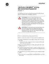
Figure 1.1
1203-GK5 Module and 1336-GM5 Board
The 1203-GK5 module mounts on a DIN rail and connects to the
SCANport product via a SCANport cable. The 1336-GM5 board
mounts directly onto selected SCANport products and connects to the
SCANport product via an internal connector.
Both types of DeviceNet communications adapters provide an
electronic communications interface between a DeviceNet network
and any single SCANport product.
1203-GK5 Module
1336-GM5 Board
AB0933
efesotomasyon.com - Allen Bradley,Rockwell,plc,servo,drive

1-2 Overview
Figure 1.2
Example DeviceNet Network
In Figure 1.2, Node 1 and Node 2 use a 1203-GK5 module to connect
to the DeviceNet network, and Node 3 uses a 1336-GM5 board to
connect to it. SCANport cables connect 1203-GK5 modules to their
SCANport products. DeviceNet cables connect the modules and
board to the DeviceNet network. The modules and board then convert
DeviceNet messages into SCANport messages for the product.
Features of the 1203-GK5 Module
and 1336-GM5 Board
The DeviceNet network is an open, global industry-standard
communication network designed to provide an interface through a
single cable from a programmable controller directly to “smart”
devices such as sensors, push buttons, motor starters, and drives.
The 1203-GK5 module and 1336-GM5 board let you connect your
SCANport products to a DeviceNet network. They feature the
following:
• DIP switches let you configure the module or board before
connecting it to the network. (The module or board can also be
configured using parameters which software tools such as
DeviceNet Manager, RSNetWorx™ for DeviceNet, and
DriveExplorer™ can access.)
• Faulted Node Recovery lets you change the node address of a
device when it is bus-off on the network. (This feature requires
the support of proper software tools, and DIP switches SW 2-7
and SW 2-8 must be set to the On position.)
• User fault response configuration provides the ability to
customize the adapter actions to communication errors.
• LEDs help to diagnose network and SCANport product health.
• With simple polling operation, the adapter can pass I/O between a
controller and SCANport product.
DeviceNet
1305
SMC
1336 PLUS
PLC-5
Node 0
Node 1
Node 2
Node 3
1336-
GM5
efesotomasyon.com - Allen Bradley,Rockwell,plc,servo,drive

Overview 1-3
SCANport Products Some SCANport products support only one peripheral; others support
up to six peripherals. The table below lists many SCANport products,
the number of peripherals each supports, the minimum and maximum
I/O words, and the type of adapter that can be used.
Important: To connect multiple peripherals to a SCANport product,
a port expander may be required. Refer to your product
documentation for more information.
Important: If you intend to use datalinks to communicate with and
control your SCANport product, verify that your SCANport product
supports datalinks before enabling them in the adapter. Each datalink
can be used by only one adapter at a time, so make sure that a datalink
is not being used by another adapter before enabling it.
Product
Number of
Peripherals
Supported
I/O Words Adapter Use
Minimum Maximum 1203-GK5 1336-GM5
1305 AC MICRO Drive 5 2 10 Yes No
1336 IMPACT™ Drive
6
➀
210Yes
Ye s
➁
1336 PLUS AC Drive
6
➀
210Yes
Ye s
➁
1336 PLUS II Drive
6
➀
210YesYes
1336 FORCE™ Drive
6
➀
210Yes
Ye s
➂
1336 SPIDER Drive
6
➀
210YesYes
1394 AC Mult-Axis Motion Control
System
5210YesNo
SMC Dialog Plus 1 2 2 Yes No
SMP-3 Smart Motor Protector 2 2 2 Yes No
1397 Digital DC Drive 5 2 10 Yes No
1557 Medium Voltage Drive 5 2 10 Yes No
➀ Lower horsepower products may not support a sixth peripheral. Refer to the user manual to verify that your product supports
a sixth peripheral.
➁ Lower horsepower products may not support an internal mounted 1336-GM5 board. Refer to the product user manual.
➂ Drive must be 30 hp or above, and it must use a standard adapter board.
efesotomasyon.com - Allen Bradley,Rockwell,plc,servo,drive

1-4 Overview
Hardware and Parts Description The hardware included with the adapter depends on the adapter that
you have.
1203-GK5 Module Hardware
Figure 1.3 illustrates and the following table lists the main parts of the
1203-GK5 DeviceNet communications module:
Figure 1.3
Parts of the 1203-GK5 Module
4
3
1
2
AB0935
Number Part Description
1 DeviceNet Connection Provides a 5-pin Phoenix connector to attach the module to the network.
2 Bi-Color LEDs Indicate the status of the DeviceNet media channel and of the SCANport connection. For
more information, refer to Chapter 7, Troubleshooting.
3 SCANport Connection Provides a standard SCANport 8-pin circular mini-DIN connector for the SCANport cable.
4 DIN Rail Mount Securely attaches and electronically grounds the module to the DIN rail.
Not
Shown
DIP Switches Located on the bottom of the module, these switches are used to configure the module. For
more information, refer to Chapter 2, Configuring the 1203-GK5 Module or 1336-GM5 Board.
Not
Shown
5-Pin Plug-In
Connector
This part is supplied with the module. The 5-pin plug-in connector is a connector to attach to
the DeviceNet cable.
Not
Shown
10-Pin Plug-In
Connector
This part is supplied with the module. The 10-pin plug-in connector is a connector to attach to
the DeviceNet cable.
efesotomasyon.com - Allen Bradley,Rockwell,plc,servo,drive

Overview 1-5
1336-GM5 Board Hardware
Figure 1.4 illustrates and the following table lists the main parts of the
1336-GM5 DeviceNet communications board:
Figure 1.4
Parts of the 1336-GM5 Board
Overview of Setting Up the
1203-GK5 Module or 1336-GM5
Board
To set up the 1203-GK5 module or 1336-GM5 board, you must
perform the following tasks:
1. Set the node address and configure the parameters. Refer to
Chapter 2, Configuring the 1203-GK5 Module or 1336-GM5
Board.
2. Install the module or mount the board. Refer to Chapter 3,
Installing the 1203-GK5 Module or 1336-GM5 Board.
3. Configure a scanner (either PLC or SLC) to communicate with
the new node. Refer to Chapter 4, Configuring a Scanner to
Communicate with the 1203-GK5 Module or 1336-GM5 Board.
4. If necessary, create a ladder logic program to control the
SCANport product. Refer to Chapter 5, Creating a Ladder Logic
Program.
1
2
3
AB0936
4
Number Part Description
1 DeviceNet Connection Provides a 5-pin Phoenix connector to attach the module to the DeviceNet network.
2 Bi-Color LEDs Indicate the status of the DeviceNet media channel and of the SCANport connection. For more
information, refer to Chapter 7, Troubleshooting.
3 SCANport Connection Provides a 14-pin connector containing power and SCANport communication circuitry.
4 DIP Switches Located on the bottom of the module, these switches are used to configure the module. For
more information, refer to Chapter 2, Configuring the 1203-GK5 Module or 1336-GM5 Board.
Not
Shown
Kit Provides the necessary materials for mounting the board to the SCANport product. These
materials include one grounding wrist strap, four Phillips mounting screws, four stand-off nylon
headers, one 5-pin connector, and one snap-in comm housing with mounting instructions.
efesotomasyon.com - Allen Bradley,Rockwell,plc,servo,drive

1-6 Overview
Required Tools and Equipment The tools and equipment required, depend on if you are using a
1203-GK5 module or 1336-GM5 board.
1203-GK5 Module
When unpacking the 1203-GK5 module, ensure that the contents of
the shipping box include:
• 1203-GK5 DeviceNet Communications Module.
• 5-pin and 10-pin plug-in connector.
• DeviceNet Communications Module User Manual.
To install the 1203-GK5 module, ensure that you have the following
tools and equipment:
• 35 x 7.5 mm DIN rail A.
• 1/8" flathead screwdriver.
• Appropriate cables for SCANport and DeviceNet connections.
Refer to the “Selecting Cables” section in Chapter 3, Installing
the 1203-GK5 Module or 1336-GM5 Board.
• A computer that is:
– Running DeviceNet Manager or RSNetWorx for DeviceNet.
– Connected to and communicating with the DeviceNet
network using an available computer to DeviceNet interface
such as a 1784-PCD card or a 1770-KFD adapter.
– Able to connect to a PLC or SLC.
– Running RSLinx.
– Running RSLogix5 (if using PLC) or RSLogix500 (if using
SLC).
Important: Refer to http://www.software.rockwell.com for more
information on these software products.
efesotomasyon.com - Allen Bradley,Rockwell,plc,servo,drive

Overview 1-7
1336-GM5 Board
When unpacking the 1336-GM5 board, ensure that the contents of the
shipping box include:
• 1336-GM5 DeviceNet Communications Board.
• One 5-pin plug-in connector.
• One grounding wrist strap.
• Four Phillips mounting screws.
• Four stand-off nylon headers.
• One snap-in communications housing with mounting
instructions.
• DeviceNet Communications Module User Manual.
To install and configure a 1336-GM5 board, ensure that you have the
following tools and equipment:
• #1 Phillips screwdriver.
• Appropriate cable for the DeviceNet connection. Refer to the
“Selecting Cables” section in Chapter 3, Installing the 1203-GK5
Module or 1336-GM5 Board.
• A computer that is:
– Running DeviceNet Manager or RSNetWorx for DeviceNet.
– Connected to and communicating with the DeviceNet
network using an available computer to DeviceNet interface
such as a 1784-PCD card or a 1770-KFD adapter.
– Able to connect to a PLC or SLC.
– Running RSLinx.
– Running RSLogix5 (if using PLC) or RSLogix500 (if using
SLC).
Important: Refer to http://www.software.rockwell.com for more
information on these software products.
efesotomasyon.com - Allen Bradley,Rockwell,plc,servo,drive

1-8 Overview
This Page Intentionally Left Blank.
efesotomasyon.com - Allen Bradley,Rockwell,plc,servo,drive
/