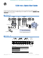
Allen-Bradley 1336 PLUS II Quick start guide
- Type
- Quick start guide
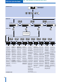
Allen-Bradley 1336 PLUS II is an adjustable frequency AC drive designed to control the speed of AC motors. It offers a range of features that make it suitable for various industrial applications, including:
-
Easy installation and setup: The drive comes with a Quick Start Guide that provides step-by-step instructions for installation, startup, and programming.
-
Digital and analog inputs and outputs: The drive has several digital and analog inputs and outputs that allow for flexible control and monitoring of the motor.
-
Built-in protection features: The drive includes various protection features to prevent damage to the motor and the drive itself. These features include overcurrent, overvoltage, and undervoltage protection.


-
 1
1
-
 2
2
-
 3
3
-
 4
4
-
 5
5
-
 6
6


Allen-Bradley 1336 PLUS II Quick start guide
- Type
- Quick start guide
Allen-Bradley 1336 PLUS II is an adjustable frequency AC drive designed to control the speed of AC motors. It offers a range of features that make it suitable for various industrial applications, including:
-
Easy installation and setup: The drive comes with a Quick Start Guide that provides step-by-step instructions for installation, startup, and programming.
-
Digital and analog inputs and outputs: The drive has several digital and analog inputs and outputs that allow for flexible control and monitoring of the motor.
-
Built-in protection features: The drive includes various protection features to prevent damage to the motor and the drive itself. These features include overcurrent, overvoltage, and undervoltage protection.
Ask a question and I''ll find the answer in the document
Finding information in a document is now easier with AI
Related papers
-
Allen-Bradley 1305-AA04A User manual
-
Allen-Bradley PowerFlex 40P User manual
-
-
-
-
-
-
-
-
Other documents
-
 Rockwell Automation 1336 PLUS Operating instructions
-
 Rockwell Automation Allen-Bradley 1397 User manual
-
Rockwell Automation Allen Bradley 22B-A8P0x104 User manual
-
Rockwell PowerFlex 70 User manual
-
 Rockwell Automation PowerFlex 700S User manual
-
 Rockwell Automation PowerFlex series User manual
-
 Rockwell Automation PowerFlex 700S Migration Manual
-
-
 Rockwell Automation PowerFlex 700S Programming Manual
-
 Rockwell Automation PowerFlex 700S Reference guide


