Page is loading ...

Kinetix 6000 Multi-axis
Servo Drive
Catalog Numbers
2094-AC05-MP5, 2094-AC05-M01,
2094-AC09-M02, 2094-AC16-M03,
2094-AC32-M05, 2094-BC01-MP5,
2094-BC01-M01, 2094-BC02-M02,
2094-BC04-M03, 2094-BC07-M05
2094-AC05-MP5-S, 2094-AC05-M01-S,
2094-AC09-M02-S, 2094-AC16-M03 -S,
2094-AC32-M05-S, 2094-BC01-MP5-S,
2094-BC01-M01-S, 2094-BC02-M02-S,
2094-BC04-M03-S, 2094-BC07-M05-S
2094-AMP5, 2094-AM01, 2094-AM02,
2094-AM03, 2094-AM05, 2094-BMP5,
2094-BM01, 2094-BM02, 2094-BM03,
2094-BM05
2094-AMP5-S, 2094-AM01-S,
2094-AM02-S, 2094-AM03-S,
2094-AM05-S, 2094-BMP5-S,
2094-BM01-S, 2094-BM02-S,
2094-BM03-S, 2094-BM05-S
2094-BSP2
User Manual

Important User Information
Solid state equipment has operational characteristics differing from those of
electromechanical equipment. Safety Guidelines for the Application,
Installation and Maintenance of Solid State Controls (publication SGI-1.1
available from your local Rockwell Automation sales office or online at
http://literature.rockwellautomation.com
) describes some important
differences between solid state equipment and hard-wired electromechanical
devices. Because of this difference, and also because of the wide variety of
uses for solid state equipment, all persons responsible for applying this
equipment must satisfy themselves that each intended application of this
equipment is acceptable.
In no event will Rockwell Automation, Inc. be responsible or liable for
indirect or consequential damages resulting from the use or application of
this equipment.
The examples and diagrams in this manual are included solely for illustrative
purposes. Because of the many variables and requirements associated with
any particular installation, Rockwell Automation, Inc. cannot assume
responsibility or liability for actual use based on the examples and diagrams.
No patent liability is assumed by Rockwell Automation, Inc. with respect to
use of information, circuits, equipment, or software described in this manual.
Reproduction of the contents of this manual, in whole or in part, without
written permission of Rockwell Automation, Inc., is prohibited.
Throughout this manual, when necessary, we use notes to make you aware
of safety considerations.
Allen-Bradley, CompactLogix, ControlLogix, DriveExplorer, Kinetix, RSLogix, RSLogix 5000, SoftLogix, SCANport, and Rockwell
Automation are trademarks of Rockwell Automation, Inc.
Trademarks not belonging to Rockwell Automation are property of their respective companies.
WARNING
Identifies information about practices or circumstances that can cause
an explosion in a hazardous environment, which may lead to personal
injury or death, property damage, or economic loss.
IMPORTANT
Identifies information that is critical for successful application and
understanding of the product.
ATTENTION
Identifies information about practices or circumstances that can lead
to personal injury or death, property damage, or economic loss.
Attentions help you identify a hazard, avoid a hazard, and recognize
the consequence
SHOCK HAZARD
Labels may be located on or inside the equipment, for example, a drive
or motor, to alert people that dangerous voltage may be present.
BURN HAZARD
Labels may be located on or inside the equipment, for example, a drive
or motor, to alert people that surfaces may be at dangerous
temperatures.

3 Publication 2094-UM001A-EN-P — September 2006
Preface
About This Publication. . . . . . . . . . . . . . . . . . . . . . . . . . . . . 9
Who Should Use this Manual . . . . . . . . . . . . . . . . . . . . . . . . 9
Conventions Used in This Manual . . . . . . . . . . . . . . . . . . . . 9
Additional Resources . . . . . . . . . . . . . . . . . . . . . . . . . . . . . . 10
Chapter 1
Start
Introduction . . . . . . . . . . . . . . . . . . . . . . . . . . . . . . . . . . . . 11
About the Kinetix 6000 Drive System . . . . . . . . . . . . . . . . . . 12
Catalog Number Explanation . . . . . . . . . . . . . . . . . . . . . . . . 16
Agency Compliance. . . . . . . . . . . . . . . . . . . . . . . . . . . . . . . 16
CE Requirements (System without LIM) . . . . . . . . . . . . . . 17
CE Requirements (System with LIM) . . . . . . . . . . . . . . . . 17
Chapter 2
Planning the Kinetix 6000 Drive
System Installation
Introduction . . . . . . . . . . . . . . . . . . . . . . . . . . . . . . . . . . . . 19
System Design Guidelines . . . . . . . . . . . . . . . . . . . . . . . . . . 20
System Mounting Requirements. . . . . . . . . . . . . . . . . . . . 20
Transformer Selection . . . . . . . . . . . . . . . . . . . . . . . . . . . 21
Circuit Breaker/Fuse Selection. . . . . . . . . . . . . . . . . . . . . 22
Enclosure Selection. . . . . . . . . . . . . . . . . . . . . . . . . . . . . 23
Minimum Clearance Requirements . . . . . . . . . . . . . . . . . 26
Minimizing Electrical Noise . . . . . . . . . . . . . . . . . . . . . . . . . 27
Bonding Modules . . . . . . . . . . . . . . . . . . . . . . . . . . . . . . 27
Bonding Multiple Subpanels . . . . . . . . . . . . . . . . . . . . . . 29
Establishing Noise Zones . . . . . . . . . . . . . . . . . . . . . . . . 30
Cable Categories for Kinetix 6000 Systems . . . . . . . . . . . . 37
Noise Reduction Guidelines for Drive Accessories . . . . . . 39
Chapter 3
Mounting the Kinetix 6000 Drive
System
Introduction . . . . . . . . . . . . . . . . . . . . . . . . . . . . . . . . . . . . 43
Using 2094 Mounting Brackets . . . . . . . . . . . . . . . . . . . . 43
Installing the 2094 Power Rail . . . . . . . . . . . . . . . . . . . . . 44
Determining Mounting Order . . . . . . . . . . . . . . . . . . . . . . . . 44
Mounting the Modules . . . . . . . . . . . . . . . . . . . . . . . . . . . . . 45
Mounting the External Shunt Module . . . . . . . . . . . . . . . . . . 48
Chapter 4
Kinetix 6000 Connector Data
Introduction . . . . . . . . . . . . . . . . . . . . . . . . . . . . . . . . . . . . 49
Locating IAM/AM Connectors and Indicators. . . . . . . . . . . . . 50
Safe-off Connector Pinout . . . . . . . . . . . . . . . . . . . . . . . . 52
I/O Connector Pinout . . . . . . . . . . . . . . . . . . . . . . . . . . . 54
Motor Feedback Connector Pinouts. . . . . . . . . . . . . . . . . 55
Auxiliary Feedback Connector Pinouts . . . . . . . . . . . . . . 57
IAM Input Connector Pinouts . . . . . . . . . . . . . . . . . . . . . 58
IAM and AM Motor Power and Brake Connector Pinouts . 59
Table of Contents

Publication 2094-UM001A-EN-P — September 2006
4 Table of Contents
Understanding IAM/AM Signal Specifications. . . . . . . . . . . . 60
Digital Inputs . . . . . . . . . . . . . . . . . . . . . . . . . . . . . . . . 60
SERCOS Connections . . . . . . . . . . . . . . . . . . . . . . . . . . 61
Analog Outputs . . . . . . . . . . . . . . . . . . . . . . . . . . . . . . 62
Contactor Enable Relay . . . . . . . . . . . . . . . . . . . . . . . . . 63
Motor/Resistive Brake Relay . . . . . . . . . . . . . . . . . . . . . 64
Control Power Input . . . . . . . . . . . . . . . . . . . . . . . . . . . 65
Understanding Feedback Specifications. . . . . . . . . . . . . . . . 66
Motor and Auxiliary Feedback Specifications . . . . . . . . . 66
Feedback Power Supply . . . . . . . . . . . . . . . . . . . . . . . . 67
Locating Shunt Module Connectors and Indicators. . . . . . . . 68
Chapter 5
Connecting the Kinetix 6000 Drive
System
Introduction. . . . . . . . . . . . . . . . . . . . . . . . . . . . . . . . . . . . 69
Understanding Basic Wiring Requirements . . . . . . . . . . . . . 69
Building Your Own Cables . . . . . . . . . . . . . . . . . . . . . . 70
Routing Power and Signal Wiring . . . . . . . . . . . . . . . . . 70
Determining Your Type of Input Power . . . . . . . . . . . . . . . 71
Grounded Power Configurations . . . . . . . . . . . . . . . . . . 71
Ungrounded Power Configurations . . . . . . . . . . . . . . . . 73
DC Common Bus Configurations . . . . . . . . . . . . . . . . . . . . 74
Common Bus Fusing Requirements . . . . . . . . . . . . . . . . 75
Setting the Ground Jumper in Ungrounded
Power Configurations . . . . . . . . . . . . . . . . . . . . . . . . . . . 75
Setting the Ground Jumper . . . . . . . . . . . . . . . . . . . . . . 76
Grounding Your Kinetix 6000 System . . . . . . . . . . . . . . . . . 78
Grounding Your System to the Subpanel . . . . . . . . . . . . 78
Grounding Multiple Subpanels . . . . . . . . . . . . . . . . . . . 79
Power Wiring Requirements . . . . . . . . . . . . . . . . . . . . . . . . 80
Wiring Guidelines . . . . . . . . . . . . . . . . . . . . . . . . . . . . . . . 83
Wiring the LIM Connectors. . . . . . . . . . . . . . . . . . . . . . . . . 84
Wiring the Auxiliary Input Power (APL) Connector. . . . . 84
Wiring the VAC LINE (IPL) Connector . . . . . . . . . . . . . . 85
Wiring the VAC LOAD (OPL) Connector . . . . . . . . . . . . 86
Wiring the Control Power Output (CPL) Connector . . . . 87
Wiring the Auxiliary Power Output (P2L) Connector . . . 88
Wiring the Brake Power Output (24V dc) Connector . . . 89
Wiring the IAM/AM Connectors . . . . . . . . . . . . . . . . . . . . . 90
Wiring the Control Power (CPD) Connector. . . . . . . . . . 90
Wiring the Input Power (IPD) Connector . . . . . . . . . . . . 91
Wiring the Contactor Enable (CED) Connector . . . . . . . . 93
Wiring the Safe-off (SO) Connector . . . . . . . . . . . . . . . . 94
Wiring the Motor Power (MP) Connector . . . . . . . . . . . . 95
Wiring the Motor/Resistive Brake (BC) Connector . . . . . 101
Applying the Motor Cable Shield Clamp . . . . . . . . . . . . . . . 103
Understanding Feedback and I/O Cable Connections . . . . . 104
Flying-lead Feedback Cable Pin-outs . . . . . . . . . . . . . . . 105

Publication 2094-UM001A-EN-P — September 2006
Table of Contents 5
Wiring Feedback and I/O Connectors. . . . . . . . . . . . . . . . . 108
Connecting Premolded Motor Feedback Cables . . . . . . . 108
Wiring Panel-mounted Breakout Board Kits. . . . . . . . . . 109
Wiring Low-profile Connector Kits . . . . . . . . . . . . . . . . 110
Understanding External Shunt Module Connections. . . . . . . 113
Understanding Resistive Brake Module Connections . . . . . . 114
Connecting Your SERCOS Fiber-optic Cables . . . . . . . . . . . 115
Chapter 6
Configure and Startup the
Kinetix 6000 Drive System
Introduction . . . . . . . . . . . . . . . . . . . . . . . . . . . . . . . . . . . 119
Configure the IAM/AM. . . . . . . . . . . . . . . . . . . . . . . . . . . . 120
Configure the Logix SERCOS interface Module . . . . . . . . . . 125
Configure the Logix Controller . . . . . . . . . . . . . . . . . . . 125
Configure the Logix Module . . . . . . . . . . . . . . . . . . . . . 126
Configure the Kinetix 6000 Modules . . . . . . . . . . . . . . . 128
Configure the Motion Group. . . . . . . . . . . . . . . . . . . . . 132
Configure Axis Properties . . . . . . . . . . . . . . . . . . . . . . . 133
Download the Program. . . . . . . . . . . . . . . . . . . . . . . . . 134
Apply Power to the Kinetix 6000 Drive. . . . . . . . . . . . . . . . 135
Test and Tune the Axes . . . . . . . . . . . . . . . . . . . . . . . . . . . 138
Test the Axes . . . . . . . . . . . . . . . . . . . . . . . . . . . . . . . . 138
Tune the Axes . . . . . . . . . . . . . . . . . . . . . . . . . . . . . . . 141
Chapter 7
Troubleshooting the Kinetix 6000
Drive System
Introduction . . . . . . . . . . . . . . . . . . . . . . . . . . . . . . . . . . . 145
Safety Precautions . . . . . . . . . . . . . . . . . . . . . . . . . . . . . . . 145
Interpreting Status Indicators . . . . . . . . . . . . . . . . . . . . . . . 146
Error Codes . . . . . . . . . . . . . . . . . . . . . . . . . . . . . . . . . 146
IAM/AM Status Indicators . . . . . . . . . . . . . . . . . . . . . . . 152
SM Status Indicators . . . . . . . . . . . . . . . . . . . . . . . . . . . 153
Troubleshooting General System Problems . . . . . . . . . . . . . 155
Understanding Logix/Drive Fault Behavior . . . . . . . . . . 157
Supplemental Troubleshooting Information . . . . . . . . . . . . 160
Tools for Changing Parameters . . . . . . . . . . . . . . . . . . . 160
Using Analog Test Points to Monitor System Variables . . 161
Chapter 8
Removing and Replacing the
Kinetix 6000 Drive Modules
Introduction . . . . . . . . . . . . . . . . . . . . . . . . . . . . . . . . . . . 163
Before You Begin . . . . . . . . . . . . . . . . . . . . . . . . . . . . . . . 163
Removing Power Rail Modules . . . . . . . . . . . . . . . . . . . . . . 164
Replacing Power Rail Modules . . . . . . . . . . . . . . . . . . . . . . 165
Removing the Power Rail. . . . . . . . . . . . . . . . . . . . . . . . . . 166
Replacing the Power Rail . . . . . . . . . . . . . . . . . . . . . . . . . . 167

Publication 2094-UM001A-EN-P — September 2006
6 Table of Contents
Appendix A
Specifications and Dimensions
Introduction. . . . . . . . . . . . . . . . . . . . . . . . . . . . . . . . . . . . 169
Power Specifications . . . . . . . . . . . . . . . . . . . . . . . . . . . . . 170
Integrated Axis Module (converter) Power Specifications 170
Axis Module (inverter) Power Specifications. . . . . . . . . . 172
Shunt Module Power Specifications . . . . . . . . . . . . . . . . 173
Circuit Breaker/Fuse Specifications . . . . . . . . . . . . . . . . 177
Contactor Ratings . . . . . . . . . . . . . . . . . . . . . . . . . . . . . 179
Transformer Specifications for Control Power Input . . . . 179
Power Dissipation Specifications. . . . . . . . . . . . . . . . . . . . . 180
General Specifications . . . . . . . . . . . . . . . . . . . . . . . . . . . . 181
Maximum Feedback Cable Lengths . . . . . . . . . . . . . . . . 181
Environmental Specifications . . . . . . . . . . . . . . . . . . . . . 181
Weight Specifications . . . . . . . . . . . . . . . . . . . . . . . . . . 182
Certifications. . . . . . . . . . . . . . . . . . . . . . . . . . . . . . . . . 182
AC Line Filter Specifications . . . . . . . . . . . . . . . . . . . . . . . . 183
External Shunt Module Specifications . . . . . . . . . . . . . . . . . 184
Product Dimensions . . . . . . . . . . . . . . . . . . . . . . . . . . . . . . 185
Appendix B
Interconnect Diagrams
Introduction. . . . . . . . . . . . . . . . . . . . . . . . . . . . . . . . . . . . 191
Wiring Examples . . . . . . . . . . . . . . . . . . . . . . . . . . . . . . . . 192
Power Wiring Examples . . . . . . . . . . . . . . . . . . . . . . . . 193
DC Common Bus Wiring Examples . . . . . . . . . . . . . . . . 197
Shunt Module Wiring Examples. . . . . . . . . . . . . . . . . . . 201
Axis Module/Motor Wiring Examples. . . . . . . . . . . . . . . 204
Controlling a Brake Example. . . . . . . . . . . . . . . . . . . . . 210
System Block Diagrams . . . . . . . . . . . . . . . . . . . . . . . . . . . 212
Appendix C
Upgrading Firmware
Introduction. . . . . . . . . . . . . . . . . . . . . . . . . . . . . . . . . . . . 215
Using ControlFLASH Software to Upgrade Drive Firmware. . 216
Before You Begin . . . . . . . . . . . . . . . . . . . . . . . . . . . . . 216
Selecting the Drive to Upgrade . . . . . . . . . . . . . . . . . . . 217
Configuring Logix Communications . . . . . . . . . . . . . . . . 218
Flashing Firmware . . . . . . . . . . . . . . . . . . . . . . . . . . . . 220
Troubleshooting ControlFLASH . . . . . . . . . . . . . . . . . . . 222
Verifying the Firmware Upgrade . . . . . . . . . . . . . . . . . . 223
Using DriveExplorer Software to Upgrade Drive Firmware. . 224
Before You Begin . . . . . . . . . . . . . . . . . . . . . . . . . . . . . 224
Selecting Axis Modules to Upgrade . . . . . . . . . . . . . . . . 224
HyperTerminal Configuration . . . . . . . . . . . . . . . . . . . . 226
Flashing Firmware . . . . . . . . . . . . . . . . . . . . . . . . . . . . 228

Publication 2094-UM001A-EN-P — September 2006
Table of Contents 7
Appendix D
DC Common Bus Applications
Introduction . . . . . . . . . . . . . . . . . . . . . . . . . . . . . . . . . . . 231
Before You Begin . . . . . . . . . . . . . . . . . . . . . . . . . . . . . . . 231
Calculating Total Bus Capacitance . . . . . . . . . . . . . . . . . . . 232
Calculating Additional Bus Capacitance . . . . . . . . . . . . . . . 232
Kinetix 6000 Capacitance Values . . . . . . . . . . . . . . . . . . . . 233
Common Bus Capacitance Example . . . . . . . . . . . . . . . . . . 234
Setting the Additional Bus Capacitance Parameter . . . . . . . . 235
Removing SERCOS Communication. . . . . . . . . . . . . . . . 235
Setting the Additional Bus Capacitance Parameter . . . . . 236
Saving the Add Bus Cap Parameter to
Non-Volatile Memory. . . . . . . . . . . . . . . . . . . . . . . . . 237
Reconnecting SERCOS Communication . . . . . . . . . . . . . 238
Appendix E
Integrating Resistive Brake
Modules with Kinetix 6000 Drives
Introduction . . . . . . . . . . . . . . . . . . . . . . . . . . . . . . . . . . . 239
Before You Begin . . . . . . . . . . . . . . . . . . . . . . . . . . . . . . . 239
Understanding Safety Precautions. . . . . . . . . . . . . . . . . . . . 240
Safety Standards for Reference . . . . . . . . . . . . . . . . . . . 240
Background on Safety Design . . . . . . . . . . . . . . . . . . . . 241
Stop Categories . . . . . . . . . . . . . . . . . . . . . . . . . . . . . . 241
Risk Assessment . . . . . . . . . . . . . . . . . . . . . . . . . . . . . . 242
Control Reliability. . . . . . . . . . . . . . . . . . . . . . . . . . . . . 243
Resistive Brake Module Wiring Examples . . . . . . . . . . . . . . 243
Setting the RBM Delay Time Using DriveExplorer . . . . . . . . 252
Removing SERCOS Communication. . . . . . . . . . . . . . . . 252
Setting the RBM Delay Time Parameter . . . . . . . . . . . . . 253
Saving the Delay Time Parameter to
Non-Volatile Memory. . . . . . . . . . . . . . . . . . . . . . . . . 254
Reconnecting SERCOS Communication . . . . . . . . . . . . . 255

Publication 2094-UM001A-EN-P — September 2006
8 Table of Contents

9 Publication 2094-UM001A-EN-P — September 2006
Preface
Read this preface to familiarize yourself with the rest of the manual.
About This Publication
This manual provides detailed installation instructions for mounting,
wiring, and troubleshooting your Kinetix 6000 drive, and system
integration for your drive/motor combination with a Logix controller.
Who Should Use this
Manual
This manual is intended for engineers or technicians directly involved
in the installation and wiring of the Kinetix 6000 drive, and
programmers directly involved in the operation, field maintenance,
and integration of the Kinetix 6000 drive with a SERCOS interface
module.
If you do not have a basic understanding of the Kinetix 6000 drive,
contact your local Rockwell Automation sales representative before
using this product, for information on available training courses.
Conventions Used in This
Manual
The conventions starting below are used throughout this manual.
• Bulleted lists such as this one provide information, not procedural
steps
• Numbered lists provide sequential steps or hierarchical
information
• Acronyms for the Kinetix 6000 drive components, shown in the
table below, are used throughout this manual.
Kinetix 6000 Component Catalog Numbers Acronym
Integrated Axis Module 2094-xCxx-Mxx IAM
Axis Module 2094-xMxx AM
Shunt Module 2094-BSP2 SM
Power Rail 2094-PRx PR
Power Rail (slim) 2094-PRSx PRS
Power Rail Slot Filler 2094-PRF PRF
Line Interface Module 2094-xLxx and -xLxxS-xx LIM
Resistive Brake Module 2090-XBxx-xx RBM

Publication 2094-UM001A-EN-P — September 2006
10
Additional Resources
The following documents contain additional information concerning
related Allen-Bradley products.
You can view or download publications at
http://literature.rockwellautomation.com
. To order paper copies of
technical documentation, contact your local Rockwell Automation
distributor or sales representative.
For Read This Document Publication Number
Information on the installation of your Bulletin 2094 Power Rail Kinetix 6000 Power Rail Installation Instructions 2094-IN003
Information on the installation and troubleshooting of your
Bulletin 2094 Line Interface Module (LIM)
Line Interface Module Installation Instructions 2094-IN005
Information on the installation of Bulletin 2094 Mounting
Brackets
2094 Mounting Bracket Installation Instructions 2094-IN008
Information on the installation and wiring of Bulletin 2090
Resistive Brake Modules
Resistive Brake Module Installation Instructions 2090-IN009
Information on proper handling, installing, testing, and
troubleshooting fiber-optic cables
Fiber-optic Cable Installation and Handling Instructions 2090-IN010
Information on installing, configuring, and how to calculate the
data needed to correctly select a 1336 dynamic brake
1336 Dynamic Braking Installation Instructions 1336-5.64
Information, examples, and techniques designed to minimize
system failures caused by electrical noise
System Design for Control of Electrical Noise Reference
Manual
GMC-RM001
EMC Noise Management DVD GMC-SP001
Information on wiring and troubleshooting your Kinetix 6000
safety drive
Kinetix Safe-off Feature Safety Reference Manual GMC-RM002
Specifications, motor/servo-drive system combinations, and
accessories for Kinetix motion control products
Kinetix Motion Control Selection Guide GMC-SG001
Drive and motor sizing with application analysis software Motion Analyzer CD, v4.2 or later PST-SG003
Information on configuring and troubleshooting your
ControlLogix and CompactLogix SERCOS interface modules
Motion Modules in Logix5000 Control Systems User
Manual
LOGIX-UM002
Information on configuring and troubleshooting your SoftLogix
PCI card
SoftLogix Motion Card Setup and Configuration Manual 1784-UM003
Information on installing, configuring, programming, and
operating a ControlLogix system
ControlLogix Controllers User Manual 1756-UM001
More detailed information on the use of ControlLogix motion
features and application examples
ControlLogix Motion Module Programming Manual 1756-RM086
The instructions needed to program a motion application
Logix5000 Controllers Motion Instructions Reference
Manual
1756-RM007
For ControlFLASH information not specific to any drive family ControlFLASH Firmware Upgrade Kit User Manual 1756-6.5.6
Online product selection and system configuration tools,
including AutoCAD (DXF) drawings
Rockwell Automation Configuration and Selection Tools
website
http://www.ab.com/
e-tools
For declarations of conformity (DoC) currently available from
Rockwell Automation
Rockwell Automation Product Certification website
http://
www.rockwellautomation.
com/products/certification
An article on wire sizes and types for grounding electrical
equipment
National Electrical Code
Published by the National
Fire Protection Association
of Boston, MA.
A glossary of industrial automation terms and abbreviations Rockwell Automation Industrial Automation Glossary AG-7.1

11 Publication 2094-UM001A-EN-P — September 2006
Chapter
1
Start
Introduction
Use this chapter to become familiar with the Kinetix 6000 drive
components. This chapter also reviews design and installation
requirements for Kinetix 6000 drive systems.
Topic Page
Introduction 11
About the Kinetix 6000 Drive System 12
Catalog Number Explanation 16
Agency Compliance 16

Publication 2094-UM001A-EN-P — September 2006
12 Start
About the Kinetix 6000
Drive System
The Kinetix 6000 multi-axis servo drive is designed to provide a
Kinetix Integrated Motion solution for applications with output power
requirements between 3 and 45 kW (4 and 49 A).
Kinetix 6000 Drive System Overview
Kinetix 6000
Component
Catalog Numbers Description
Integrated Axis
Module
2094-xCxx-Mxx-S
(1)
Integrated Axis Module (IAM), with safe-off feature available with 230V and 460V ac input power and
contains an inverter and converter.
2094-xCxx-Mxx
Integrated Axis Module (IAM), available with 230V and 460V ac input power and contains an inverter
and converter.
Axis Module
2094-BMxx-S
(1)
Axis Module (AM), with safe-off feature is a shared dc bus inverter (230V and 460V). The AM must be
used with an IAM.
2094-xMxx Axis Module (AM), is a shared dc bus inverter (230V and 460V). The AM must be used with an IAM.
Shunt Module 2094-BSP2
Shunt Module (SM), This module mounts to the power rail and provides additional shunting capability in
regenerative applications.
Power Rail
2094-PRSx
2094-PRx
Power Rail (PR) consists of copper bus bars and a circuit board with connectors for each module. The
power rail provides power and control signals from the converter section to adjacent inverters. The IAM,
AM, SM, and PRF modules mount to the power rail.
Power Rail Slot
Filler
2094-PRF
Power Rail Slot Filler (PRF) is used when one or more slots on the power rail are empty after all the
power rail components are installed. One PRF module is required for each empty slot.
Logix Controller
Platform
1756-MxxSE module
1768-M04SE module
1784-PM16SE PCI card
SERCOS interface module/PCI card serves as a link between the ControlLogix/CompactLogix/SoftLogix
platform and Kinetix 6000 drive system. The communication link uses the IEC 61491 SErial Real-time
COmmunication System (SERCOS) protocol over a fiber-optic cable.
RSLogix 5000
Software
9324-RLD300ENE
RSLogix 5000 provides support for programming, commissioning, and maintaining the Logix family of
controllers.
Servo Motors
MP-Series, 1326AB,
TL-Series,
F- and Y-Series
Compatible servo motors include the MP-Series (Low Inertia, Integrated Gear, Food Grade, and Stainless
Steel) 230 and 460V motors; TL-Series motors; 1326AB (M2L/S2L) and 1326AB (resolver) motors; F- and
Y-Series motors.
Cables
Motor Power, Feedback,
and Brake cables
Motor power, feedback, and brake cables include integral molded, bayonet style, quick connect/
quick-release connectors at the motor. Power and brake cables have flying leads on the drive end and
straight connectors that connect to servo motors. Standard feedback cables have angled connectors
(45º) on the drive end and straight connectors that connect to servo motors. Optional feedback cables
have a straight connector on the motor end and flying leads that wire to a low-profile connector kit on
the drive end.
Fiber-optic cables
SERCOS fiber-optic cables are available in enclosure only, PVC, nylon, and glass with connectors at both
ends.
AC Line Filters 2090-XXLF-xxxx
Bulletin 2090-XXLF-xxxx three-phase ac line filters are required to meet CE and available for use in 230V
and 460V systems.
Line Interface
Module
2094-xLxx
2094-xLxxS
2094-XL75S-Cx
Line Interface Module (LIM), contains the circuit breakers, ac line filter (2094-AL09 and -BL02 only),
power supplies, and safety contactor required for Kinetix 6000 operation. This module does not mount to
the power rail. Individual components can be purchased separately in place of the LIM.
External Shunt
Modules
1394-SRxxxx
Bulletin 1394 external passive shunt modules can be used when the IAM/AM internal shunt and power
rail mounted shunt module (2094-BSP2) capability is exceeded.
1336-MOD-Kxxxx
Bulletin 1336 external active shunt modules can be used when the internal shunt resistor (IAM/AM)
capability is exceeded.
Resistive Brake
Module
2090-XBxx-xx
Resistive Brake Module (RBM), includes a safety contactor for use in a control circuit. Contactors and
resistors reside in this module such that the motor leads can be disconnected from the drive with the
permanent magnet motor brought to an immediate stop. This module does not mount to the power rail.
(1)
Refer to the Kinetix Safe-off Feature Safety Reference Manual, publication GMC-RM002, for more information.

Publication 2094-UM001A-EN-P — September 2006
Start 13
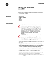
Typical Kinetix 6000 system installations include three-phase ac
configurations, with and without the line interface module (LIM), and
dc common bus configurations.
Typical Kinetix 6000 System Installation (with LIM)
SHOCK HAZARD
To avoid personal injury due to electrical shock, place a slot
filler module (catalog number 2094-PRF) in all empty slots on
the power rail.
Any power rail connector without a module installed will
disable the Kinetix 6000 three-phase power, however control
power is still present.
SERCOS interface
TM
Tx (rear)
Rx (front)
OK
CP
MAIN VAC
Logix SERCOS interface Module
Logix Controller Programming Network
Kinetix 6000 Multi-axis Servo Drive System
Line Interface Module
(optional component)
2094-xLxxS
Axis Modules (5)
2094-xMxx-S
Three-phase
Input Power
Integrated
Axis Module
2094-xCxx-Mxx-S
Shunt Module
(optional component)
2094-BSP2
Motor Feedback Cable
2090-XXNFxx-Sxx
Motor Power Cable
2090-XXNPxx-xxSxx
AC Line Filter
2090-XXLF-xxxx
Power Rail
2094-PRSx
Slot Filler
Module
(required to
fill any unused
slots)
2094-PRF
MP-Series, TL-Series, 1326AB (M2L/S2L),
F- and Y-Series Motors
(MPL-xxxx motors shown)
I/O Connections
To input sensors
and control string.
115/230V Control Power
Low Profile Connector Kits for
I/O, Motor Feedback, and Aux Feedback
2090-K6CK-Dxxx
SERCOS Fiber-optic Ring
2090-SCxxx-x
Logix Platform
(ControlLogix is shown)
RSLogix 5000
Software

Publication 2094-UM001A-EN-P — September 2006
14 Start
Typical Kinetix 6000 System Installation (without LIM)
Kinetix 6000 Multi-axis Servo Drive System
SERCOS Fiber-optic Ring
2090-SCxxx-x
Line
Disconnect
Device
Magnetic
Contactor
Input
Fusing
Three-phase
Input Power
Single-phase
Control Power
Integrated
Axis Module
2094-xCxx-Mxx-S
Motor Feedback Cable
2090-XXNFxx-Sxx
Power Rail
2094-PRSx
MP-Series, TL-Series, 1326AB (M2L/S2L),
F- and Y-Series Motors
(MPL-xxxx motors shown)
I/O Connections
To input sensors
and control string.
Axis Modules (5)
2094-xMxx-S
Shunt Module
(optional component)
2094-BSP2
Motor Power Cable
2090-XXNPxx-xxSxx
Slot Filler
Module
(required to
fill any unused
slots)
2094-PRF
AC Line Filter
2090-XXLF-xxxx
Low Profile Connector Kits for
I/O, Motor Feedback, and Aux Feedback
2090-K6CK-Dxxx
Logix SERCOS interface Module
Logix Platform
(ControlLogix is shown)
RSLogix 5000
Software
Logix Controller Programming Network

Publication 2094-UM001A-EN-P — September 2006
Start 15
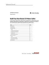
Typical DC Common Bus System Installation
In the example above, the leader IAM is connected to the follower
IAM via the dc common bus. When planning your panel layout, you
must calculate the total bus capacitance of your dc common bus
system to ensure that the leader IAM is sized sufficiently to pre-charge
the entire system.
Refer to Appendix D, beginning on page 231, for more information.
SERCOS interface
Tx (rear)
Rx (front)
OK
CP
Logix SERCOS interface Module
Logix Platform
(ControlLogix is shown)
RSLogix 5000
Software
Logix Controller Programming Network
Kinetix 6000 Multi-axis Servo Drive System
SERCOS Fiber-optic Ring
2090-SCxxx-x
Three-phase
Input Power
115/230V Control Power
Integrated
Axis Module
2094-xCxx-Mxx-S
Power Rail
(2094-PRSx is shown)
Axis Modules (5)
2094-xMxx-S
Shunt Module
(optional component)
2094-BSP2
Slot Filler Module
(required to fill any
unused slots)
2094-PRF
Integrated
Axis Module
2094-xCxx-Mxx-S
Axis Modules (5)
2094-xMxx-S
Slot Filler Module
(required to fill any
unused slots)
2094-PRF
SERCOS Fiber-optic Ring
2090-SCxxx-x
Line Interface Module
(optional component)
2094-xLxxS
AC Line Filter
2090-XXLF-xxxx
DC Common Bus
Power Rail
(2094-PRSx is shown)
Motors and other details common to both three-phase
ac and dc common bus configurations are removed.
IMPORTANT
If total bus capacitance of your system exceeds the leader IAM
pre-charge rating and input power is applied, the IAM
seven-segment LED indicator will display error code E90
(pre-charge timeout fault). To correct this condition, you must
replace the leader IAM with a larger module or decrease the
total bus capacitance by removing axis modules.

Publication 2094-UM001A-EN-P — September 2006
16 Start
Catalog Number
Explanation
Kinetix 6000 drive catalog numbers and descriptions are listed in the
table below.
Kinetix 6000 Drive Catalog Numbers
Agency Compliance
If this product is installed within the European Union or EEC regions
and has the CE mark, the following regulations apply.
Integrated Axis Modules (230V
Catalog Number
(with safe-off feature)
Catalog Number
(without safe-off feature)
Kinetix 6000, IAM, 230V, 3 kW converter, 5 A inverter 2094-AC05-MP5-S 2094-AC05-MP5
Kinetix 6000, IAM, 230V, 3 kW converter, 9 A inverter 2094-AC05-M01-S 2094-AC05-M01
Kinetix 6000, IAM, 230V, 6 kW converter, 15 A inverter 2094-AC09-M02-S 2094-AC09-M02
Kinetix 6000, IAM, 230V, 11 kW converter, 24 A inverter 2094-AC16-M03-S 2094-AC16-M03
Kinetix 6000, IAM, 230V, 23 kW converter, 49 A inverter 2094-AC32-M05-S 2094-AC32-M05
Integrated Axis Modules (460V)
Kinetix 6000, IAM, 460V, 6 kW converter, 4 A inverter 2094-BC01-MP5-S 2094-BC01-MP5
Kinetix 6000, IAM, 460V, 6 kW converter, 9 A inverter 2094-BC01-M01-S 2094-BC01-M01
Kinetix 6000, IAM, 460V, 15 kW converter, 15 A inverter 2094-BC02-M02-S 2094-BC02-M02
Kinetix 6000, IAM, 460V, 28 kW converter, 30 A inverter 2094-BC04-M03-S 2094-BC04-M03
Kinetix 6000, IAM, 460V, 45 kW converter, 49 A inverter 2094-BC07-M05-S 2094-BC07-M05
Axis Modules (230V)
Kinetix 6000, AM, 230V, 5 A 2094-AMP5-S 2094-AMP5
Kinetix 6000, AM, 230V, 9 A 2094-AM01-S 2094-AM01
Kinetix 6000, AM, 230V, 15 A 2094-AM02-S 2094-AM02
Kinetix 6000, AM, 230V, 24 A 2094-AM03-S 2094-AM03
Kinetix 6000, AM, 230V, 49 A 2094-AM05-S 2094-AM05
Axis Modules (460V)
Kinetix 6000, AM, 460V, 4 A 2094-BMP5-S 2094-BMP5
Kinetix 6000, AM, 460V, 9 A 2094-BM01-S 2094-BM01
Kinetix 6000, AM, 460V, 15 A 2094-BM02-S 2094-BM02
Kinetix 6000, AM, 460V, 30 A 2094-BM03-S 2094-BM03
Kinetix 6000, AM, 460V, 49 A 2094-BM05-S 2094-BM05
Shunt Module
Kinetix 6000, SM, 230V/460V, 200W N/A 2094-BSP2
ATTENTION
Meeting CE requires a grounded system, and the method of
grounding the ac line filter and drive must match. Failure to do
this renders the filter ineffective and may cause damage to the
filter.
For grounding examples, refer to Grounded Power
Configurations on page 71.

Publication 2094-UM001A-EN-P — September 2006
Start 17
For more information on electrical noise reduction, refer to the System
Design for Control of Electrical Noise Reference Manual, publication
GMC-RM001.
CE Requirements (System without LIM)
To meet CE requirements when your Kinetix 6000 system does not
include the line interface module (LIM), the following requirements
apply.
• Install an ac line filter (2090-XXLF-xxxx) as close to the integrated
axis module (IAM) as possible.
• Use 2090 series motor power cables or use connector kits and
terminate the cable shields to the chassis clamp provided.
• Combined motor power cable length for all axes on the same dc
bus must not exceed 240 m (787 ft) with 460V systems or 160 m
(525 ft) with 230V systems. Drive-to-motor power cables must not
exceed 90 m (295.5 ft).
• Use 2090 series motor feedback cables or use connector kits and
properly terminate the feedback cable shield. Drive-to-motor
feedback cables must not exceed 90 m (295.5 ft).
• Install the Kinetix 6000 system inside an enclosure. Run input
power wiring in conduit (grounded to the enclosure) outside of
the enclosure. Separate signal and power cables.
Refer to Chapter 5, beginning on page 69, for wiring instructions and
the Kinetix Motion Control Selection Guide, publication GMC-SG001,
for catalog numbers.
CE Requirements (System with LIM)
To meet CE requirements when your Kinetix 6000 system includes the
line interface module (LIM), follow all the requirements as stated in
CE Requirements (System without LIM) and these additional
requirements as they apply to the ac line filter.
• Install the LIM (2094-AL09 or -BL02) as close to the integrated axis
module (IAM) as possible.
• Install the LIM (2094-ALxxS, -BLxxS or -XL75S-Cx) with line filter
(2090-XXLF-xxxx) as close to the IAM as possible.
When the LIM (2094-ALxxS, -BLxxS or -XL75S-Cx) supports two
IAMs, each IAM requires an ac line filter installed as close to the
IAM as possible.

Publication 2094-UM001A-EN-P — September 2006
18 Start

19 Publication 2094-UM001A-EN-P — September 2006
Chapter
2
Planning the Kinetix 6000 Drive System
Installation
Introduction
This chapter describes system installation guidelines used in
preparation for mounting your Kinetix 6000 drive components.
Topic Page
Introduction 19
System Design Guidelines 20
Minimizing Electrical Noise 27
ATTENTION
Plan the installation of your system so that you can perform all
cutting, drilling, tapping, and welding with the system removed
from the enclosure. Because the system is of the open type
construction, be careful to keep any metal debris from falling
into it. Metal debris or other foreign matter can become lodged
in the circuitry, which can result in damage to components.

Publication 2094-UM001A-EN-P — September 2006
20 Planning the Kinetix 6000 Drive System Installation
System Design Guidelines
Use the information in this section when designing your enclosure
and planning to mount your system components on the panel.
For on-line product selection and system configuration tools,
including AutoCAD (DXF) drawings of the product, refer to
http://www.ab.com/e-tools.
System Mounting Requirements
• In order to comply with UL and CE requirements, the Kinetix 6000
system must be enclosed in a grounded conductive enclosure
offering protection as defined in standard EN 60529 (IEC 529) to
IP55 such that they are not accessible to an operator or unskilled
person. A NEMA 4X enclosure exceeds these requirements
providing protection to IP66.
• The panel you install inside the enclosure for mounting your
system components must be on a flat, rigid, vertical surface that
won’t be subjected to shock, vibration, moisture, oil mist, dust, or
corrosive vapors.
• Size the drive enclosure so as not to exceed the maximum
ambient temperature rating. Consider heat dissipation
specifications for all drive components.
• Segregate input power wiring and motor power cables from
control wiring and motor feedback cables. Use shielded cable for
power wiring and provide a grounded 360° clamp termination.
• Use high-frequency (HF) bonding techniques to connect the
modules, enclosure, machine frame, and motor housing, and to
provide a low-impedance return path for high-frequency (HF)
energy and reduce electrical noise.
Refer to the System Design for Control of Electrical Noise
Reference Manual, publication GMC-RM001, to better understand
the concept of electrical noise reduction.
/