Page is loading ...

Instructions
This document provides information on upgrading the 1336 PLUS II
firmware, including a description of the Flash memory used in the
drive and the procedures required for downloading the latest firmware
revision. For detailed drive information, refer to 1336
PLUS II User
Manual, publication 1336 PLUS-5.3.
What is Flash Memory?
The drive firmware (including parameter layout and operating
algorithms) resides in a form of programmable read-only memory
called “Flash Memory.” Flash memory allows the user to easily
upgrade the drive firmware locally using a standard computer and the
supplied Firmware Download Module. The latest firmware files are
available on the Internet or from your local Allen-Bradley Sales
Office.
Firmware Download
Requirements
The necessary file can be downloaded to the module with a computer
having the following:
• Disk drive (hard and/or floppy).
• Standard communications program capable of XMODEM
protocol.
• Standard serial “COM” port and connecting cable (see below).
In addition, the following is recommended:
• IBM
compatible computer with Microsoft
Windows
Operating
System.
• Internet access and browser software.
Required Communications
Cable
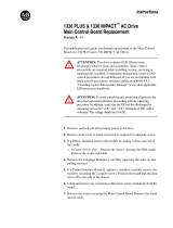
A standard serial communications cable wired as shown, is required.
This cable interconnects the computer and Flash Download Module.
Flash Download Module
9 Pin Female
D-Shell Connector
PC COM Port
9 Pin Male
D-Shell Connector
1
1
6
6
7
7
8
8
2
2
33
4
4
5
5
9
9
TX
RX
COM
1336 PLUS II Firmware Download
Module
Catalog Number 1336F-FDM
Allen-Bradley Replacements

2 1336 PLUS II Firmware Download Module
Main Control Board Power
Requirements
In order to upgrade firmware, the Main Control Board must have
power applied. This can be accomplished through one of the
following methods:
• Application of AC line voltage per instructions in Chapter 2 of
the 1336
PLUS II User Manual. This is the normal method for
installed drives.
• External power supply through the auxiliary 24V DC input at
terminal block TB4 (B frame & up, see Auxiliary Inputs – TB4,
TB6 in the User Manual).
• External power supply through power connector on module (all
drives). This method does not power the entire logic section, but
provides enough power to activate the flash memory. This is the
best method for drives not yet installed. The external supply must
provide 6.0 - 9.0V DC, 0.5A and is connected on the right-side of
the module (see Figure 1).
Important:
Do Not apply power until instructed to do so.
Installation Procedure Important:
During the time that the flash memory is being upgraded,
the drive will be in a “non-operational state” and will not
havetheabilitytocontrolthemotor.Becertainthatplacing
the drive in a non-operational state is acceptable.
1. Remove and lock-out all incoming power to the drive.
2. If a HIM (or other snap-in module) is installed, remove it by
carefully squeezing the locking tabs-in and pulling-out.
3. A Frame Drives - If a Control Interface Board (L option) is
installed, carefully remove the board by loosening the 2 captive
screws. Position the board and attached wires off to the side of the
chassis.
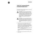
4. Locate a spare jumper on the Main Control Board and install it at
J20 (see Figure 1). This jumper allows the flash EEPROM to be
overwritten with a new version of firmware.
!
ATTENTION: This drive and module contain ESD
(Electrostatic Discharge) sensitive parts and assemblies.
Static control precautions are required when installing,
testing, servicing or repairing this assembly. Component
damage may result if ESD control procedures are not
followed. If you are not familiar with static control
procedures, reference publication 8000-4.5.2, “Guarding
AgainstElectrostaticDamage”oranyotherapplicableESD
protection handbook.
!
ATTENTION: To avoid a shock hazard, assure that all
power to the drive has been removed before proceeding. In
addition, verify that the DC bus has discharged by
measuring across the “+DC” and “–DC” terminals of TB1
with a voltmeter. The voltage should be 0.0VDC.

1336 PLUS II Firmware Download Module 3
Figure 1
Component Locations
5. Install the Flash Download Module in the Main Control Board
cradle – place the guide tab into the slot, making sure the module
connector lines up with the connector on the Main Control Board.
Press the module until the 4 locking tabs lock in place.
6. Connect the communications cable (refer to page 1) between the
9 pin D-Shell Communications Connector on the Flash
Download Module and the selected computer COM port.
7. Apply power using one of the methods described on page 2.
When power is applied, the POWER SUPPLY and STOP status
LEDs on the Main Control Board should illuminate. If an
external power supply is used, the FAULT LED may also be
illuminated.
Obtaining the Files Copying the Files to the Computer
8. This procedure assumes that you are using Windows
95. The
procedure may vary if a different computer/operating system is
used.
A. If you obtained the file on a floppy disk, verify that you have
the correct file using the information in step C. Then proceed
to step 9.
B. Using an Internet browser such as Netscape Navigator
or
Microsoft
Internet Explorer, access the 1336 PLUS II
download page on the World Wide Web at:
http://www.ab.com/drives
then select . . .
“
Software
” followed by . . .
“
Flash ROM Updates
”
The files available for downloading will be listed.
Frames A1 - A4
Frames B - G
J20
J14
Spare Jumpers
Status LEDs
Status LEDs
Spare Jumpers
Flash
Download Module
External Power Connector
Communications Connector
Control Interface Option Location
J20
J14
ANALOG I/O
SLOT B
8642
7531
J10
ANALOG I/O
SLOT A
86
7531
J9
POWER
SUPPLY
RUN
STOP
FAULT
POWER
SUPPLY
RUN
STOP
FAULT
ANALOG I/O
SLOT B
8642
7531
J10
ANALOG I/O
SLOT A
86
7531
J9
Allen-Bradley Replacements

4 1336 PLUS II Firmware Download Module
C. Verify the files using the information below.
To properly complete all download functions, certain
information contained in a “readme” file must be read and
recorded. The “readme” file will have the same version
number and a “.txt” file type (i.e. Read1004.txt). You should
obtain both files (i.e. V_x.xxxf.bin and Readxxxx.txt).
Important:
Verify that the “.bin” file has an “f”
(V_x.xxx
f.xxx). If you cannot locate the correct
file, contact your local Sales Office.
If you obtained the files on a floppy disk, proceed to step 9.
D. Select the first file to initiate the save dialog box. Select a
convenient location on your computer to save the file, then
choose “Save.” Repeat for the second file. Exit your browser
software.
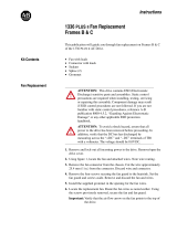
9. Locate the readme file on your computer using Windows
Explorer. “Double-click” on the file to open/view it. The file
information will be displayed on the screen, along with any notes
concerning software changes or installation tips.
Record the information below and close the window.
V_ 1 . 004 f .bin
Version
Major Revision
Level
Minor Revision
Level
Serial Flash
Version File Type
Major rev levels
may include new
features, updated
drive identification
(newly released
sizes) or software
corrections.
Minor revs may
include corrections
to languages, etc.
The file for a 1336
PLUSII Drivemust
have an “f.”
bin=binary
txt=text
Item Readme File Information
Current Drive Firmware
(will be completed in Step 15)
File Name
Firmware Revision
Boot Block
DSP Main Block

1336 PLUS II Firmware Download Module 5
Establishing Communications
with the Drive
Setting Up the Communications Program
10. Start the XMODEM communications program. The following
examples demonstrate the use of HyperTerminal (supplied with
Windows 95 operating system). Other programs will be similar.
From the Start menu, choose:
“
Programs -> Accessories -> HyperTerminal
”
11. With the Hyperterminal window active, double click the
Hypertrm.exe
icon
A.
Connection Description window
– enter a name and select
“OK.”
Allen-Bradley Replacements

6 1336 PLUS II Firmware Download Module
B.
Phone Number window
– locate the Connect using: menu and
choose “Direct to Com1,” then select “OK.” If a different
COM port is being used, substitute the appropriate one for
your computer setup.
C.
COM Properties window
– locate the Bits per second menu
and choose “9600” (default of the drive). Choose “None” for
Flow control and then select “OK.”

1336 PLUS II Firmware Download Module 7
Transferring the File to the Drive
12. Press the Enter key on your computer once to signal the drive –
an introduction screen will be displayed.
13. Press “F” to enter the Flash Mode. You are now prompted to
confirm your choice “Are you sure?” (y or n).
Important:
During the time that the flash memory is being
upgraded,thedrivewillbeina“non-operationalstate”
and will not have the ability to control the motor. Be
certainthat placing the drivein a non operationalstate
is acceptable.
Press “Y” to place the drive in flash mode (the Power LED on the
module will illuminate). Press “Enter” to continue.
Allen-Bradley Replacements

8 1336 PLUS II Firmware Download Module
14. The default baud rate of 9600 should be acceptable under most
conditions. However, to facilitate faster file transfers, the baud
rate can be changed for communications up to the maximum
drive rate of 115.2 kb (or the maximum computer rate). To use
the default rate, proceed to step 15.
A. Select “
(3) Set Baud rate
” by pressing the “3” key.
B. Select the desired baud rate and note instructions displayed
on the screen.
C. Select “Exit” from the HyperTerminal File menu. Repeat
steps 10 through 13 to change the COM port baud rate to
match the rate just selected.
15. Select “
(1) Display Drive information
” by pressing the “1” key.
This will cause the drive to display information about the current
firmware versions of both the microprocessor and the Digital
Signal Processor (DSP).
The screen will display Firmware Revision ID for the
microprocessor (which runs most of the features), the DSP Main
Block program (runs the majority of drive functions) and DSP
Boot Block (controls the DSP). The program you download may
or may not have a change to the DSP Main Block (covered later
in this procedure).
Record this data in step 9 on page 4, then compare the data. If the
two DSP Main Block revision levels are different, be aware that
further actions will be required in step 19 on page 11.

1336 PLUS II Firmware Download Module 9
16. Select “
(2) Send File to drive
.” A message will appear regarding
correct jumper installation. A string of C’s will then appear,
indicating that the drive is waiting for the file to be downloaded.
17. From the Transfer menu (top of screen), select “Send File.” Enter
the file path (location of .bin file) and choose “Xmodem” as the
protocol, then select “Send.”
The download process will continue until complete. The screen
will be updated as progress continues. The STOP LED on the
Main Control Board will flicker or blink, indicating
communications. If an error message is received, refer to Table
A, “General Troubleshooting,” on page 12.
Important:
Do not interrupt the download procedure. If the
procedure is interrupted, the program in the drive will
be corrupted. The procedure must then be repeated.
Allen-Bradley Replacements

10 1336 PLUS II Firmware Download Module
If the “packet” value is not incrementing and the time remaining
block is continually incrementing, the file transfer is not taking
place. If this occurs, cancel the operation and repeat the entire
procedure, verifying jumper placement, cabling and
communications setup.
When the transfer is complete, the screen will indicate that the
file was successfully transferred and checksums are complete.

1336 PLUS II Firmware Download Module 11
18. If errors occurred in the transfer, the screen may display one of
the following:
• Error in Constant Block
• Error in Program Block
• Error in DSP Block
• Error in Text and Language Block
If errors are indicated, press the Enter key on the computer and
return to step 10 on page 5 to repeat the entire process from that
point.
19. If no errors have occurred . . .
A. Remove all power from the drive and wait 60 seconds for the
bus to discharge.
B. Remove the communications cable from the module and
computer. Remove the Flash Download Module by grasping
the 4 locking tabs, then squeeze the tabs and pull the module
towards you.
C. Remove jumper J20 (installed in step 4 on page 2) and place
in spare jumper location.
D. If a new DSP Main Block is included in the downloaded file
(check information recorded in step 9 on page 4), a DSP file
image resides in flash memory. However, this image will not
be downloaded to the DSP until jumper J14 is installed and
drive power is applied. If J14 is not installed, a DSP Protected
fault (F46) will occur on power-up.
Locate a spare jumper on the Main Control Board and install
it at J14 (see Figure 1).
E. Reinstall the HIM or communications option and the Control
Interface Board, if previously removed.
F. Apply power to the drive. One of the following conditions
should occur:
G. Use a felt tip pen to mark the new Software Revision number
on the Main Control Board label.
20. Download is complete! Place this document with your User
Manual for future reference.
Condition Action then . . .
Drive active. No faults. If J14 is installed Power down and remove J14. Procedure is complete
If J14 is Not installed Procedure is complete
EE Init or other EE fault
occurs
Use the HIM EEPROM Menu
to reset the drive to factory
defaults
If J14 is installed Powerdownand removeJ14.
Procedure is complete
if J14 is Not installed Procedure is complete
DSP Protected (F46) fault Install jumper J14 Cycle power a second time. Powerdownand removeJ14.
Process complete
HIM Continuously displays
“Connecting….Connecting….
Repeat entire procedure
Allen-Bradley Replacements

12 1336 PLUS II Firmware Download Module
Troubleshooting Table A
General Troubleshooting
Table B
Drive Related Faults
Netscape Navigator is a registered trademark of Netscape Communications Corporation
IBM is a registered trademark of International Business Machines Corporation
Microsoft, MS-DOS and Windows are registered trademarks of Microsoft Corporation
Condition Cause Action
“Transfer cancelled by remote system” Jumper J20 not installed. End the communications session, remove power from
the drive and return to Step 4 on page 2.
“Error from Flash is 1” Jumper J20 not installed. End the communications session, remove power from
the drive and return to Step 4 on page 2.
No Communications
Communications to the drive cannot
be established.
Baud rates of computer and drive do
not match.
or
Jumpers are not properly installed.
or
Cables are incorrect
Remove drive power and allow bus voltage to decay to
zero. Then reset computer baud rate to 9600 and return
to step 10 on page 5.
Power down the drive, allowing bus voltage to decay to
zero. Return to step 4 on page 2 for proper jumper
installation.
Recheck cable pinout against the diagram on page 1.
File is not transferred.
File transfer screen appears but no
data changes and no action occurs.
Xmodem was not chosen as the
transfer protocol.
Return to step 17 on page 9 and choose Xmodem as
the protocol.
Main Menu is unreadable
Main Menu and other communications
from the drive are unreadable.
Baud rates of computer and drive do
not match.
Remove drive power and allow bus voltage to decay to
zero. Then reset computer baud rate to 9600 and return
to step 10 on page 5.
Condition Cause Action
DSP Protected Fault (F46) A new DSP file image was downloaded
to the flash memory. On power-up, the
drive attempted to download this image
to the DSP, but jumper J14 (DSP
Program Allow) was not installed.
Remove power. Install J14.
Reapply power. Confirm DSP transfer by comparing
recorded values from step 9 on page 4 to HIM values
for parameters 300 and/or 301 in the Linear List.
Remove and reapply power a second time.
EE Init Read (F53) User parameter values stored on
EEPROM are incompatible with new
parameters.
Use EEPROM Mode to Reset the drive to Factory
Defaults. Cycle power. Reprogram if necessary.
EE Init Value (F54) User parameter values stored on
EEPROM are incompatible with new
parameters.
Use EEPROM Mode to Reset the drive to Factory
Defaults. Cycle power. Reprogram if necessary.
Rockwell Automation helps its customers receive a superior return on their investment by bringing
together leading brands in industrial automation, creating a broad spectrum of easy-to-integrate
products. These are supported by local technical resources available worldwide, a global network
of system solutions providers, and the advanced technology resources of Rockwell.
Worldwide representation.
Argentina • Australia • Austria • Bahrain • Belgium • Bolivia • Brazil • Bulgaria • Canada • Chile • China, People’s Republic of • Colombia • Costa Rica • Croatia • Cyprus
Czech Republic • Denmark • Dominican Republic • Ecuador • Egypt • El Salvador • Finland • France • Germany • Ghana • Greece • Guatemala • Honduras • Hong Kong
Hungary • Iceland • India • Indonesia • Iran • Ireland • Israel • Italy • Jamaica • Japan • Jordan • Korea • Kuwait • Lebanon • Macau • Malaysia • Malta • Mexico
Morocco • The Netherlands • New Zealand • Nigeria • Norway • Oman • Pakistan • Panama • Peru • Philippines • Poland • Portugal • Puerto Rico • Qatar • Romania • Russia
Saudi Arabia • Singapore • Slovakia • Slovenia • South Africa, Republic of • Spain • Sweden • Switzerland • Taiwan • Thailand • Trinidad • Tunisia • Turkey • United Arab Emirates
United Kingdom • United States • Uruguay • Venezuela
Rockwell Automation Headquarters, 1201 South Second Street, Milwaukee, WI 53204-2496 USA, Tel: (1) 414 382-2000, Fax: (1) 414 382-4444
Publication 1336 PLUS-5.72 – July, 1998 P/N191148(01)
Copyright 1998 Rockwell International Corporation. All rights reserved. Printed in USA.
/