HK Instruments RHT-MOD-Series Humidity Transmitters User manual
- Type
- User manual
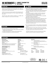
HK Instruments RHT-MOD-Series Humidity Transmitters accurately measure humidity and temperature in commercial environments, including offices, hospitals, and HVAC/R applications. With a large touchscreen display, configuration is quick and easy, allowing users to customize settings and monitor readings. The RHT-MOD-Series features a polymer capacitive sensing element for precise relative humidity measurement and an integrated sensor for temperature, providing reliable data for various applications.
HK Instruments RHT-MOD-Series Humidity Transmitters accurately measure humidity and temperature in commercial environments, including offices, hospitals, and HVAC/R applications. With a large touchscreen display, configuration is quick and easy, allowing users to customize settings and monitor readings. The RHT-MOD-Series features a polymer capacitive sensing element for precise relative humidity measurement and an integrated sensor for temperature, providing reliable data for various applications.


-
 1
1
-
 2
2
-
 3
3
-
 4
4


HK Instruments RHT-MOD-Series Humidity Transmitters User manual
- Type
- User manual
HK Instruments RHT-MOD-Series Humidity Transmitters accurately measure humidity and temperature in commercial environments, including offices, hospitals, and HVAC/R applications. With a large touchscreen display, configuration is quick and easy, allowing users to customize settings and monitor readings. The RHT-MOD-Series features a polymer capacitive sensing element for precise relative humidity measurement and an integrated sensor for temperature, providing reliable data for various applications.
Ask a question and I''ll find the answer in the document
Finding information in a document is now easier with AI
Related papers
-
 HK Instruments RHT Installation guide
-
HK Instruments CDT2000 Series User manual
-
 HK Instruments CDT-MOD-2000 Series User manual
-
 HK Instruments RHT User guide
-
-
-
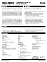
HK Instruments CDT-MOD-2000 CARBON DIOXIDE TRANSMITTERS Operating instructions
-
 HK Instruments RHT Installation guide
-
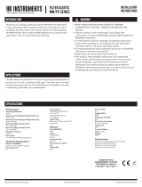 HK Instruments MM/PS Installation guide
-
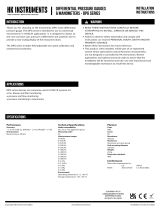 HK Instruments DPG Installation guide


Other documents
-
FläktGroup CentriFlow 3D GMPM_GMEB Built-on drive Operating instructions
-
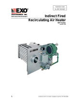 Exothermics RHT Operating instructions
-
-
-
WEG ALC11 User manual
-
Advantech APAX-5620KW User manual
-
Carel heos User manual
-
-
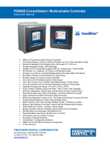 PRECISION DIGITAL PD9000 User manual
-
Danfoss VLT® HVAC Basic Drive FC 101 User guide

