Page is loading ...

IMPORTANT SAFEGUARDS
READ AND FOLLOW ALL SAFETY INSTRUCTIONS.
When using electrical equipment, basic safety precautions should always be followed including the following:
• DISCONNECT AC POWER SUPPLY BEFORE SERVICING.
• Installation and servicing of this equipment should be performed by qualified service personnel only.
• Ensure that the electrical wiring conforms to the National Electrical Code NEC® and local regulations
if applicable.
• Do not mount near gas or electrical heaters.
• Do not use outdoors.
• Equipment should be mounted in locations and at heights where it will not be readily subjected to tampering
by unauthorized personnel.
• The use of accessory equipment not recommended by the manufacturer may cause an unsafe condition.
• Any modification or use of non-original components will void the warranty and product liability.
• Do not use this equipment for other than intended use.
• Allow battery to charge for 24 hours before first use.
SAVE THESE INSTRUCTIONS!
Technical Support ■ (623) 580-8943 ■ [email protected]
QCRT Series
Installation Instructions
10070233 REV 1 - 01/21 800-533-3948 www.barronltg.com
1

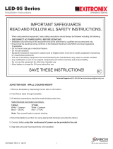
Parts Legend (Fig. 1)
a. Chevron h. Wire Nut
b. Faceplate i. Backplate
c. Diffuser j. Enclosure
d. Switch/LED Cover k. Canopy
e. PCB l. Canopy Screws
f. Battery m. J-Box Mounting Plate
g. Lamp n. Faceplate Insert
Single to Double Face Conversion
1. Push out the snap-on clips and gently slide out the backplate insert from the enclosure.
2. Slide in the EXIT faceplate and snap it in place.
Removing Directional Indicators
1. Gently pop out the color diffuser lens from the unit faceplate(s).
2. Using your fingers or a soft tool, tap/knock out the desired chevron from its position.
3. Replace the color diffuser lens onto the faceplate.
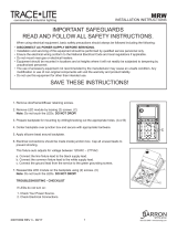
Wall Mount (Single Face Only) (Fig. 2)
Note: UL recommended maximum height is 13ft for standard and
remote capable models, 15ft for high output model.
1. Turn off AC power and remove the faceplate of the EXIT section.
2. Refer to the Removing Directional Indicators section to remove
the appropriate chevron(s) from the faceplate when required.
3. Remove the appropriate knockouts in the backplate of the fixture
to fit the J-box mounting points.
Note: These knockouts are not intended for use with conduit
fittings.
4. Feed the power supply module input wires from the sign through
the 7/8” opening in the center of the backplate. Route the wires along the side walls of the sign enclosure to ensure
proper sign illumination and to protect wires from damage.
5. Connect building supply wires to the power supply module input wires and feed splices into the junction box. Refer to
the Electrical Connections section for wiring instructions. Cap off the unused input lead.
6. Attach the backplate to the junction box using the screws provided.
7. After AC power can be continuously supplied, push in the connector from the battery to the LED board.
8. Reattach the faceplate to the sign enclosure to finish installation.
Fig. 1
Fig. 2
QCRT Series
Installation Instructions
10070233 REV 1 - 01/21 800-533-3948 www.barronltg.com
2

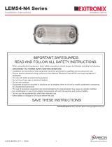
Fig. 3
Ceiling or End Mount (Fig. 3)
Note: UL recommended maximum height is 13ft for standard and
remote capable models, 15ft for high output model.
1. Turn off AC power and remove the faceplate of the EXIT section.
2. Refer to the Removing Directional Indicators section to remove
the appropriate chevron(s) from the faceplate when required.
3. Secure the mounting canopy to the sign enclosure after removing
the appropriate mounting hole cover. For end-mount installation,
remove a lamp head from the unit and attach the mounting canopy
in its place.
4. Feed the power supply module input wires from the sign through
the opening in the mounting canopy and the mounting bracket.
Route the wires along the side walls of the sign enclosure to ensure
proper sign illumination and to protect wires from damage.
5. Connect building supply wires to the power supply module input
wires and feed splices into the junction box. Refer to the Electrical Connections section for wiring instructions. Cap off
the unused input lead.
6. After AC power can be continuously supplied, push the connector from the battery into the LED board.
7. Reattach the faceplate to the sign enclosure.
8. Attach the mounting bracket to the junction box using the screws provided.
9. Securely attach the mounting canopy to the mounting bracket to finish installation.
Electrical Connections (Fig. 4 & 5)
All electrical connections should be made inside the J-box.
Make electrical connections as follows:
Note: Cap unused leads to prevent shorting.
120VAC 277VAC
White - Common White - Common
Black - 120VAC Red - 277VAC
Fig. 4 - Standard & High Output Models
Fig. 5 - Remote Capable Models
QCRT Series
Installation Instructions
10070233 REV 1 - 01/21 800-533-3948 www.barronltg.com
2
/