Page is loading ...

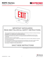
INSTRUCTIONS for Lithonia Lighting ECC Models
READ AND FOLLOW ALL SAFETY INSTRUCTIONS
SAVE THESE INSTRUCTIONS
and deliver to owner after installation
Do not use outdoors.
Do not mount near gas or electric heaters.
Equipment should be mounted in locations and at heights where it will not be subject to tampering by unauthorized personnel.
Cap unused wires with enclosed wire nuts or other approved method.
Do not use this equipment for anything other than its intended use.
IMPORTANT SAFEGUARDS:
When using electrical equipment; basic safety precautions should always be followed, including the following:
IMPORTANT:
The battery in this unit may not be fully charged. After continuous AC power is connected to the unit for at least 24 hours, then normal
operation of this unit should take effect. To check, press the “TEST” button. The EXIT sign should stay illuminated and the LED lamps
on the unit should turn on.
In accordance with NFPA 101 (current life safety code), your emergency lighting system must be tested monthly for a minimum of 30
seconds and annually for 90 minutes. Refer to your local codes for any additional requirements that may apply.
Disconnect AC power before servicing and installation.
6. The use of accessory equipment not recommended by the manufacturer may cause an unsafe condition.
Use caution when servicing batteries.
8. Consult local building code for approved wiring and installation.
10. Any service on this equipment should be performed by qualified personnel only.
Make sure wire terminations are secure and leads are properly tucked in appropriate wire channels.
1.
2.
3.
4.
5.
7.
9.
11.
READ AND FOLLOW ALL SAFETY INSTRUCTIONS
PAGE: 1 of 3
Note: Max mounting height is 8 ft to achieve at least 1 ft-candle of illuminance in emergency mode.
Exit/Unit Combo
When replacing components, use only LED lamps or lamp boards specified in the fixture.
Remote Capable Exit
DISCONTINUED

PAGE: 2 of 3
INSTALLATION INSTRUCTIONS (top or end mount):
1.
2.
De-energize the circuit at an industry standard junction box, (not included), where the exit sign is to be installed.
Remove the exit sign stencil and set aside.
Remove the canopy kit, hardware pack and mounting plate from inside the EXIT and set aside.
Remove the mounting hole plug on the top or either side of the frame .
Place the canopy nose through the mounting hole until the side of the frame touches the canopy. Lock the frame onto the
canopy by sliding the frame in a direction parallel to the canopy length toward the narrow end of the mounting hole. Slide the
frame until both snaps engage the canopy nose preventing any motion back out of the hole .
Feed the red, black and white wires through center of mounting canopy hole.
NOTE: For LLH option, continue to step #10.
Remove side mounting hole on right side. Knockout lamp head mounting hole on left side with flathead screwdriver.
Feed blue and yellow lamp head wire through side lamp head mounting hole (Step 1). Attach first lamp head to housing by
aligning tabs on lamp head assembly to lamp head mounting slots on frame of housing (Step 2). Gently push lamp head
down toward bottom of housing to lock into place. An audible click should be heard. Repeat to install remaining lamp head.
Feed lamp head wires in appropriate wire channel and connect lamp head leads to the exit sign lamp board.
Ensure fixture leads are fed through mounting canopy and connect to AC power leads coming into the junction box.
For 120V, connect BLACK lead to HOT of the power supply and for 230V or 277V connect the RED lead. Connect the WHITE lead
to the NEUTRAL of the supply. Use a wirenut to cap off the unused lead.
When applicable, make wiring connections to the appropriate remote lamp heads using the YELLOW (+) and the BLUE (-) remote
leads on the charger board. Cap off any UNUSED remote leads with wire nuts.
Secure the EXIT canopy to the steel mounting plate using the screws provided and fasten to junction box.
Connect battery only after continuous AC power can be provided to the unit.
Remove knockout(s) for Chevron(s) as needed to provide directional indication.
Secure faceplate(s) to housing.
3.
4.
5.
6.
7.
10.
11.
12.
13.
14.
15.
8.
9.
16.
FACE PLATE
CHEVRON
KNOCKOUT
EXIT SIGN
LAMP BOARD
BATTERY
HOUSING
LENS/LED(s)*
LAMP HEAD
HOUSING*
BACKPLATE
CANOPY
MOUNTING PLATE
JUNCTION BOX
MOUNTING SCREWS
LAMP HEAD*
MOUNTING
HOLE PLUG
INSTALLATION INSTRUCTIONS (back mount):
1.
2. Remove the exit sign stencil and set aside. Remove the hardware and set aside. Remove and discard the plastic canopy and
mounting plate.
De-energize the circuit at an industry standard junction box, (not included), where the exit sign is to be installed.
3.
8.
Drill out the appropriate mounting pattern and the wire pass hole in the EXIT back plate to fit the junction box being used.
Feed the red, black and white wires through the center.
NOTE: For LLH option, continue to step #8.
Remove side mounting hole plug on right side. Knockout lamp head mounting hole on left side with flathead screwdriver.
Feed blue and yellow lamp head wire through side lamp head mounting hole (Step 1). Attach first lamp head to housing by aligning tabs
on lamp head assembly to lamp head mounting slots on frame of housing (Step 2). Gently push lamp head down toward bottom of
housing to lock into place. An audible click should be heard. Repeat to install remaining lamp head.
Feed lamp head wires in appropriate wire channel and connect lamp head leads to the exit sign lamp board.
Ensure fixture leads are fed through back plate and connect to AC power leads coming into the junction box.
For 120V, connect BLACK lead to HOT of the power supply and for 230V or 277V connect the RED lead. Connect the WHITE lead to
the NEUTRAL of the supply. Use a wirenut to cap off the unused lead.
When applicable, make wiring connections to the appropriate remote lamp heads using the YELLOW (+) and the BLUE (-) remote
leads on the charger board. Cap off any UNUSED remote leads with wire nuts.
Fasten back plate to junction box cover.
Connect battery only after continuous AC power can be provided to the unit.
Remove knockout(s) for Chevron(s) as needed to provide directional indication.
Secure face plate to housing.
13.
14.
10.
11.
12.
INSTRUCTIONS for Lithonia Lighting ECC Models
*Lamp heads included on exit/unit combo models only.
DISCONTINUED

LED STATUS INDICATOR KEY and TROUBLESHOOTING
WIRING DIAGRAMS
NOTE: Unused input lead must be properly insulated with wire nut or other approved method.
STANDARD COMBO COMBO (REM OPTION)
Visual Status Indica�on Troubleshooting/Actions to Take
RED
GREEN
UNLIT
1. Battery connection is not made.
2. Battery has been diagnosed as dead or defective after 24 hours
of continuous charging with AC power supplied.
Battery is connected, AC power has been supplied and fixture is in
charging state.
AC power has not been supplied.
1. Make connection; or if battery is connected, disconnect
battery for eight seconds and then reconnect.
2. Replace the battery.
This is the normal state. No action required.
Supply AC power.
SAVE THESE INSTRUCTIONS
and deliver to owner after installation
PAGE: 3 of 3
Part No. 912-00052-001, REV C.
2019.12.02
INSTRUCTIONS for Lithonia Lighting ECC Models
STANDARD LLH LLH (REM OPTION)
f � L L®
-
An�rands Company
LIFE SAFETY SOLUTIONS
800-705-SERV {7378) www.lithonia.com
FCC Title 47,
Part 15, Subpart B
DISCONTINUED
/