1/2
WARNING: FAILURE TO FOLLOW THESE INSTRUCTIONS AND WARNINGS MAY RESULT IN DEATH, SERIOUS INJURY OR
SIGNIFICANT PROPERTY DAMAGE. FOR YOUR PROTECTION, READ AND FOLLOW THESE WARNINGS AND INSTRUCTIONS
CAREFULLY BEFORE INSTALLING OR MAINTAINING THIS EQUIPMENT. THESE INSTRUCTIONS DO NOT ATTEMPT TO
COVER ALL INSTALLATION AND MAINTENANCE SITUATIONS. IF YOU DO NOT UNDERSTAND THESE INSTRUCTIONS OR
ADDITIONAL INFORMATION IS REQUIRED, CONTACT THE MANUFACTURER.
IMPORTANT SAFEGUARDS: WHEN USING ELECTRICAL EQUIPMENT, BASIC SAFETY PRECAUTIONS SHOULD ALWAYS BE
FOLLOWED, INCLUDING THE FOLLOWING:
When re-lamping, only use lamps specied in the exit sign. Using other lamp
types may result in transformer damage or unsafe conditions. Battery in this unit
may not be fully charged. After electricity is hooked up to unit, let the battery
charge for at least 24 hours. Normal operation of this unit should then
take effect (when applicable).
• Do not use outdoors.
• Equipment should be mounted in locations and at heights where it will not be subject to tampering by
unauthorized personnel.
• Do not mount near gas or electric heaters.
• Cap unused wires with enclosed wire nuts or other approved method.
• Do not use this equipment for other than its intended use.
• The use of accessory equipment not recommended by the manufacturer will void warranty and may cause an
unsafe condition.
• Before wiring to power supply, turn off electricity at fuse or circuit breaker.
• Use caution when servicing batteries.
• Installation and servicing should be performed by qualied personnel.
• Consult local building code for approved wiring and installation.
• Make sure wire terminations are secure and leads are properly tucked in appropriate wire channels.
NEVER CONNECT TO, DISCONNECT FROM, OR SERVICE WHILE EQUIPMENT IS ENERGIZED.
Lamps are hot. Keep combustible material away from hot parts. Observe lamp
manufacture’s warnings, recommendations and restrictions on lamp operation
and maintenance. Make sure lamps are correctly installed.
(ALWAYS TURN OFF THE POWER SUPPLY FROM MAIN CIRCUIT BREAKER FIRST!)
NOTE: THE FIXTURE SHIPS STANDARD WITH THE TOGGLE SWITCH IN THE RED POSITION.
IMPORTANT
WARNING
WARNING
INSTALLATION
READ THESE INSTRUCTIONS COMPLETELY AND CAREFULLY
PT-EXL-C-R SERIES
(PT-EXL-C-R)
INSTALLATION
INSTRUCTIONS
RISK OF ELECTRIC SHOCK
RISK OF FIRE
www.portorlighting.com Specication subject to change without notice
REMOTE EMERGENCY LIGHT (IF APPLICABLE)
• Use the yellow and blue wires for the remote xture(s).
• Route the wires outside of the xture separately or with AC supply wires.
TOP MOUNT AND END MOUNT
• Remove the faceplate(s) and lenses from housing and set aside (see Fig. A).
• Remove the canopy kit, hardware pack and mounting plate and set aside.
• Remove the mounting hole plug on the top or either side of the frame.
• Place the canopy nose through the mounting hole until the side of the frame touches
the canopy.
• Lock the frame onto the canopy by sliding the frame in a direction parallel to the canopy
length toward the narrow end of the mounting hole.
• Slide the frame until both snaps engage the canopy nose preventing any motion back
out of the hole.
• Feed the red, black and white wires through the center of the mounting canopy hole.
• Remove the side mounting hole on the right side. Knockout the lamp head mounting
hole on the left side with a flathead screwdriver.
• Feed the blue and yellow lamp head wires through side lamp head mounting hole
(Step 1).
• Attach the rst lamp head to housing by aligning tabs on the lamp head assembly to
the lamp head mounting slots on frame of housing (Step 2).
• Gently twist the lamp head clockwise to lock into place. An audible click should be
heard. Repeat to install the remaining lamp head.
• Feed the lamp head wires in the appropriate wire channel and connect the lamp head
leads to the exit sign lamp board.
• Ensure xture leads are fed through mounting canopy and connect to AC power leads
coming into the junction box.
• Connect the RED lead to the HOT wire of the power supply from 120-277V. Connect the
WHITE lead to the NEUTRAL of the supply.
• Cap off any unused remote leads with wire nuts.
• Secure the canopy to the steel mounting plate using the screws provided and fasten to
the junction box.
• Toggle the switchable button to select GREEN, if applicable (see Fig. C).
• Connect the battery only after continuous AC power can be provided to the unit.
• Remove the knockout chevron(s) on the faceplate(s), as needed.
• Insert the RED (or GREEN) lens into faceplate (RED – see Fig. A or GREEN – see Fig. B).
• Be sure to keep all wires out of the way of the EXIT letters to eliminate shadows when
illuminated.
• Secure faceplate(s) to housing.
WALL MOUNT
• Remove the faceplate(s) and lenses from housing and set aside (see Fig. A).
• Drill out the appropriate mounting pattern and the wire pass hole in the backplate to t the
junction box being used.
• Feed the red, black and white wires through the center of the backplate.
• Remove the side mounting hole on the right side. Knockout the lamp head mounting hole on
the left side with a flathead screwdriver.
• Feed the blue and yellow lamp head wires through side lamp head mounting hole (Step 1).
• Attach the rst lamp head to housing by aligning tabs on the lamp head assembly to the
lamp head mounting slots on frame of housing (Step 2).
• Gently twist the lamp head clockwise to lock into place. An audible click should be heard.
Repeat to install the remaining lamp head.
• Feed the lamp head wires in the appropriate wire channel and connect the lamp head leads
to the exit sign lamp board.
• Ensure xture leads are fed through mounting canopy and connect to AC power leads
coming into the junction box.
• Connect the RED lead to the HOT wire of the power supply from 120-277V. Connect the
WHITE lead to the NEUTRAL of the supply.
• Cap off any unused remote leads with wire nuts.
• Fasten the backplate to the junction box.
• Toggle the switchable button to select GREEN, if applicable (see Fig. C).
• Connect the battery only after continuous AC power can be provided to the unit.
• Remove the knockout chevron(s) on the faceplate, as needed.
• Insert the RED (or GREEN) lens into faceplate (RED – see Fig. A or GREEN – see Fig. B)
• Be sure to keep all wires out of the way of the EXIT letters to eliminate shadows when
illuminated.
• Secure faceplate to housing.
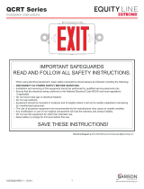
WIRING DIAGRAM
COLOR SELECTABLE LED EXIT SIGN
SAFETY AND INSTALLATION INSTRUCTIONS
Exit/Em ergency Combo Only
Exit/Em ergency Combo with Remote Head(s)
COLOR SELECTABLE LED EXIT SIGN
SAFETY AND INSTALLATION INSTRUCTIONS
Wiring Diagram
Exit/Em ergency Combo Only
Exit/Em ergency Combo with Remote Head(s)