Page is loading ...

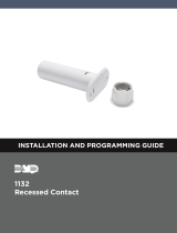
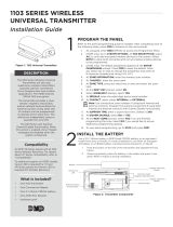
Figure 2: Battery Location and
PCB Features
DESCRIPTION
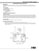
Figure 1: 1107-WINT Housing
1107-WINT WIRELESS
MICRO WINDOW TRANSMITTER
Installation Guide 1PROGRAM THE PANEL
When programming the 1107-WINT in the panel, refer to the
panel programming guide as needed.
1. In ZONE INFORMATION, enter the wireless ZONE NO:.
2. Enter the ZONE NAME.
3. Select NT (Night) as the ZONE TYPE.
4. Select the AREA.
5. At the NEXT ZONE prompt, select NO.
6. Select YES when WIRELESS? displays.
7. Enter the eight-digit SERIAL# and press CMD. See Figure
2 for the serial number location.
8. Enter the SUPRVSN TIME and press CMD.
9. At the NEXT ZN? prompt, select YES if you are finished
programming the zone. Select NO if you would like to
access additional programming options.
2INSTALL THE BATTERY
After the transmitter has been programmed into the panel, install
the battery. Use a 3.0V lithium battery, DMP Model CR2430, or
the equivalent battery from Sony or Murata. Keep in mind, when
setting up a wireless system, program zones and connect the
receiver before installing batteries in the transmitters.
1. Insert a small screwdriver into each notch in the housing
cover and lift until the cover comes o. Do not twist the
screwdriver.
2. Observing polarity, place the battery in the holder with
the positive (+) side up. Press it into place. See Figure 2
for the battery location.
The 1107-WINT Micro Window
Transmitter is a low-profile 1100INT
Series International transmitter
that can be used on windows. It is
powered by a 3.0V coin cell battery
and contains a single reed switch.
Compatibility
All DMP 1100INT Series
International Wireless Receivers
and international burglary panels.
What is Included?
• 1107-WINT Wireless
Micro Window
Transmitter
• One magnet with
a standard and a
commercial housing
• One CR2430 3.0V coin
cell lithium battery
• Double-sided tape
Battery
Location
Survey
LED Serial
Number
Internal
Reed Switch

SELECT A LOCATION
The 1107-WINT provides a survey capability to allow one person to confirm communication with the wireless
receiver or panel while the cover is removed. This allows you to easily determine the best location for the 1107-
WINT. Be sure to choose a location away from large metal objects.
1. Hold the 1107-WINT transmitter and the included magnet in the exact desired location.
2. Move the magnet away from the transmitter to send data to the receiver and determine if
communication is confirmed or faulty. See Figure 2 for the LED location.
Confirmed: If communication is confirmed, the survey LED turns on when data is sent to the
receiver and o when acknowledgement is received.
Faulty: If communication is faulty, the LED remains on for up to 8 seconds or flashes multiple
times in quick succession. Relocate the 1107-WINT or receiver until the LED confirms clear
communication. Proper communication between the 1107-WINT and receiver is verified when the
LED blinks immediately on and immediately o each time the magnet is removed.
3
MOUNT THE 1107-WINT TRANSMITTER
4Mount the 1107-WINT and magnet no more than 1/2” apart.
When mounting on metal (ferrous) surfaces, this distance is
slightly less. DMP recommends mounting the transmitter on the
window frame and the magnet assembly on the window.
1. Hold the transmitter base in place with the reed switch
alignment marker near where the magnet assembly
will be mounted. See How to Align the Transmitter and
Magnet Assembly for more information.
Note: Do not remove the PCB from the housing during
installation.
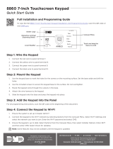
2. Place the two supplied #4 flat-head screws into the
mounting holes to secure the housing base to the surface.
See Figure 3.
3. Replace the cover.
For environments where the cover could be dislodged, the
optional #4 pan-head securing screw can be used instead of the
center flat-head screw to secure the entire transmitter and cover
to the mounting surface. See Figure 3.
For even quicker installations, use the included double-
sided tape instead of the screws to attach the housing to the
mounting surface.
HOW TO ALIGN THE TRANSMITTER AND MAGNET ASSEMBLY
When you mount the transmitter
and magnet assembly, use the
alignment markers to ensure that the
transmitter’s internal reed switch is
lined up with the magnet.
There should be no more than a
1/2” inch of space between the
transmitter and the magnet assembly.
Alignment
Markers
1/2” Max
Distance
Figure 3: Mounting
Hole Locations
Pan-Head Securing
Screw (optional)
Flat-Head
Mounting Screws
2 DIGITAL MONITORING PRODUCTS | 1107-WINT INSTALLATION GUIDE

Only one magnet assembly is required for internal reed switch
operation. Depending on the installation requirements, you can use
either the standard or commercial magnet assembly.
Standard Magnet Assembly
1. Place the magnet assembly base on the surface nearest
the transmitter’s internal reed switch location. Be sure to
align the markers on the transmitter and magnet assembly.
2. Use the provided #4 flat-head screws or included
double-sided tape to secure the base in place.
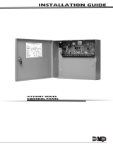
3. Snap the magnet into the magnet assembly cover, then
snap the cover onto the base. See Figure 4.
Commercial Magnet Assembly
1. Snap the magnet into the magnet assembly cover.
2. Place the cover on the surface nearest to the internal
reed switch location. Be sure to align the markers on the
transmitter and magnet assembly.
3. Use the supplied #4 flat-head screws to mount the
magnet assembly. See Figure 5.
MOUNT THE MAGNET ASSEMBLY
5
Figure 4: Standard
Magnet Assembly
Magnet
Cover
Base
Figure 5: Commercial
Magnet Assembly
Magnet
Cover
1107-WINT INSTALLATION GUIDE | DIGITAL MONITORING PRODUCTS 3
REPLACE THE BATTERY
1. Insert a small screwdriver into each notch in the housing cover and lift until the cover comes o. Do not twist the
screwdriver.
2. Remove the old battery and dispose of it properly.
3. Observing polarity, place the new battery in the holder and press into place.
4. Snap the transmitter housing cover back on the base.
Sensor Reset to Clear LOBAT
When the battery needs to be replaced, a LOBAT message will display on the keypad. Once the battery is
replaced, a sensor reset is required at the system keypad to clear the LOBAT message.
1. On a Thinline keypad, press and hold “2” for two seconds. On a touchscreen keypad press RESET.
2. Enter your user code if required.
3. The keypad displays SENSORS OFF followed by SENSORS ON.

Designed, engineered, and
manufactured in Springfield, Missouri
using U.S. and global components.
INTRUSION • FIRE • ACCESS • NETWORKS
2500 North Partnership Boulevard
Springfield, Missouri 65803-8877
866.266.2826 | DMP.com
© 2018 Digital Monitoring Products, Inc.
LT-1156INT 18095
Specifications
Battery
Life Expectancy 2 Years (normal operation)
Type 3.0V lithium CR2430
Frequency Range 863-869 MHz
Dimensions
Transmitter 6.7 L x 2.5 W x 0.8 cm
Standard Mag. 2.1 L x 1 W x 0.8 cm
Commercial Mag. 2.1 L x 1 W x 0.8 cm
Color White
Housing Material Flame-Retardant ABS
Patents
U.S. Patent No. 7,239,236
Panel Compatibility
1100X-WINT Wireless Receivers
1100D-WINT Wireless Receivers
XT30INT Series panels
XR150INT/XR550INT Series panels
International Certifications
EN 50130-4:2011+A1:2014 Alarm Systems. Electromagnetic compatibility.
Product family standard: Immunity
requirements for components of fire, intruder,
hold up, CCTV, access control and social alarm
systems.
EN 61000-6-3:2007 Electromagnetic compatibility (EMC). Generic
standards. Emission standard for residential,
commercial and light-industrial applications.
1107-WINT WIRELESS MICRO
WINDOW TRANSMITTER
/