Page is loading ...

InstallatIon GuIde
1101-WINT Universal Transmitter
Description
The 1101-WINT is a two input transmitter that is typically used for door/window applications. The 1101-WINT
provides two internal magnetic reed switches and an on-board terminal block to allow for external contact wiring.
Both sets of contacts, internal and external, can be programmed to operate at the same time allowing for two
independent zones from one transmitter. Refer to the panel programming guide for zone programming information.
Using the on-board LED the 1101-WINT Universal Transmitter provides built-in survey capability to allow for single-
person installations, eliminating the requirement for an external survey kit. A transmitter mounting bracket is
included to make the installation quick and easy. For added security, an internal case tamper switch is provided.
Compatibility
1100X-WINT Wireless Receiver
1100D-WINT Wireless Receiver
XT30INT Series panel
XR150INT/XR550INT Series panel
What is Included
The 1101-WINT Universal Transmitter includes the following
items:
• One 1101-WINT Transmitter PCB mounted in a two-part
housing (base and cover)
• One Magnet housing and base
• One 3V lithium CR123A Battery
• Hardware pack
• Zone name and number label
• Serial number label
• Optional Transmitter mounting bracket
• Optional Magnet mounting spacer
Transmitter Serial Number
For your convenience, an additional pre-printed serial number label is included. Prior to installing the device, record
the serial number or place the pre-printed serial number label on the panel programming sheet. This number is
required during programming.Asneeded,usethezonenameandnumberlabeltoidentifyaspecictransmitter.
Programming the Transmitter in the Panel
Program the device as a zone in Zone Information during panel programming. At the Serial Number: prompt, enter
the eight-digit serial number. Continue to program the zone as directed in the panel programming guide.
Note: When a receiver is installed, powered up, or the panel is reset, the supervision time for transmitters is reset.
If the receiver has been powered down for more than one hour, wireless transmitters may take up to an additional
hour to send a supervision message unless tripped, tampered, or powered up. This operation extends battery life for
transmitters. A missing message may display on the keypad until the transmitter sends a supervision message.
Selecting the Proper Location (LED Survey Operation)
The1101-WINTTransmitterprovidesasurveycapabilitytoallowonepersontoconrmtransmittercommunication
with the receiver while the cover is removed. The 1101-WINT Transmitter PCB Red Survey LED turns on whenever
data is sent to the receiver then immediately turns off when the receiver acknowledgement is received. Pressing
thetamperswitchisaconvenientwaytosenddatatothereceivertoconrmoperation.Whenthetamperswitch
is pressed or released, the LED blinks once to indicate proper operation. When the transmitter does not receive
an acknowledgement from the receiver the LED remains on for about 8 seconds to let you know communication is
notestablished.CommunicationisalsofaultywhentheLEDashesmultipletimesinquicksuccession.Relocate
the transmitter or receiver until the LED immediately turns off indicating the transmitter and receiver are
communicatingproperly.Propercommunicationbetweenthetransmitterandreceiverisveriedwhenforeachpress
orreleaseofthetamperswitch,theLEDblinksimmediatelyonandimmediatelyoff.Repeatthistesttoconrmve
separate consecutive LED blinks. Any indication otherwise means proper communication has not been established.
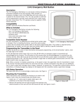
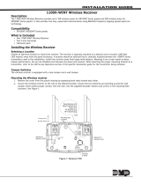
Figure 1: Mounted Transmitter and Magnet
1101-WINT Universal
Transmitter
Magnet
Housing
Ensure there is 5/8" (1.6 cm) or less
between the assembled Magnet
Housing and Transmitter Housing.
Insert small
screwdriver
and twist

Digital Monitoring Products 1101-WINT Installation Guide
2
Mounting the Transmitter and Magnet Assemblies
For internal contact operation, the transmitter and magnet assembly should have no more than 5/8" (1.6 cm)
space between the assembled housings after installation. When mounting on metal (ferrous) surfaces, this distance
is slightly less. For door installations, it is recommended the transmitter be mounted on the door frame and the
magnet assembly be mounted on the door.
Magnet Housing and Base
Only one magnet assembly is required for internal reed switch operation. Depending
on the installation, you can use either the end mount internal reed switch or side
mount internal reed switch location of the transmitter. For reference, both mounting
locations and other mounting information is included in Figures 3 and 4. An optional
magnet housing spacer is provided for installations where the magnet assembly needs
to be raised in order to line up with the reed switches in the transmitter.
Installing the Optional Mounting Bracket
The following instructions cover installing the transmitter using the mounting bracket.
If the installation does not require the mounting bracket, refer to Installing the
Transmitter without the Mounting Bracket.
1. Secure the mounting bracket using the supplied screws. Make sure the reed switch location markers are
positioned where you plan to mount and install the magnet housing.
2. Place the magnet housing base on the surface nearest to one of the internal reed switch locations and use
the provided screws to secure the magnet mounting base. If needed, set the mounting spacer below the
housing base and align the mounting holes together.
Note: The magnet housing base must be located a minimum of 1/8" (0.3 cm) from the alignment bracket. The
1/8" (0.3 cm) distance is required to ensure the magnet housing and transmitter housing have enough space
between them when mounted. When using the magnet spacer, place the spacer next to the alignment bracket.
No additional space is required between the spacer and the bracket. See Figure 3 Section B.
3. Snap the magnet housing onto the housing base.
4. Line the transmitter base up with the mounting bracket snap connectors and press the transmitter into
place.
5. The spring must be in place on the tamper switch for normal operation.
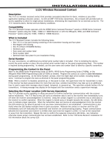
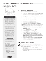
Mounting
Bracket
Magnet Housing
Base Notch
Reed Switch
Alignment Arrows
Minimum 1/8"
(0.3 cm)
Mounting Distance
Minimum 1/8" (0.3 cm)
Mounting Distance
Snap Connectors
for Transmitter
Installation
Wall Mount
Screw Holes
Alignment Bracket
(Break off for Operation)
Magnet Housing
Spacer
Mounting
Bracket
A. Optional Mounting Bracket and Magnet B. Optional Magnet Housing Spacer
Figure 3: Optional Mounting Bracket and Magnet Base and Spacer Mounting
Transmitter
Side
Mount
Magnet
End
Mount
Magnet
Figure 4: View of Side and End Mount Magnets
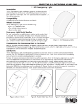
Optional
Housing Spacer
Housing
Base
Magnet
Magnet
Housing
#6 Flat Head
Mounting
Screws
Figure 2: Magnet Assembly

1101-WINT Installation Guide Digital Monitoring Products
3
Installing the Transmitter without the Mounting Bracket
These instructions cover installing the transmitter using the base housing without the mounting bracket. If the
installation requires the mounting bracket, refer to Installing the Optional Mounting Bracket above.
1. Remove the battery if installed.
2. Hold the transmitter base in place with the reed switch nearest to the area where you plan to mount the
magnet.
3. Place one supplied screw into the mounting hole location as shown in Figure 5 and secure the housing to
the surface.
4. Place the magnet housing base on the surface nearest to one of the internal reed switch locations and use
the provided screws to secure the magnet mounting base in place. See Figure 2.
5. If needed, place the magnet mounting spacer below the magnet housing base, align the holes, and use the
provided screws to secure the base and spacer in place.
6. The spring must be in place on the tamper switch for normal operation.
Internal and External Contact Mounting
When connecting an external contact to the terminal
block, DMP recommends using 18 or 22-gauge unshielded
wire. Do not use twisted pair or shielded wire. Connect
the external contact as normally open (N/O) or normally
closed (N/C) without any end-of-line resistor. Refer
to the Contact option under Zone Information in the
appropriate panel programming guide.
Note: When using both contacts, you must use
consecutive zone numbers. Refer to the following
examples:
• XR550INT system — zones 562 and 563 or zones
893 and 894
• XR150INT system — zones 523 and 524 or zones 593 and 594
• XT30INT Series — zones 31 and 32 or zones 34 and 41
Installing or Replacing the
Battery
Observe polarity when installing the
battery. Use only 3.0V lithium batteries,
DMP Model CR123, or the equivalent
battery from a local retail outlet. For
UL installations, only use #123 batteries
manufactured by Energizer or CR123A
batteries manufactured by Panasonic or
Tekcell.
Note: When setting up a wireless
system, it is recommended to program
zones and connect the receiver before installing batteries in the transmitters.
1. If installed, remove the transmitter housing cover.
2. If replacing the battery, remove the old battery and dispose of it properly.
3. Place the 3.0V lithium battery in the holder as shown in Figure 5 and press into place.
4. Line the transmitter cover so the DMP logo is over the battery and snap the cover back into place.
Caution:Riskofre,explosion,andburns.Donotrecharge,disassemble,heatabove212°F(100°C),or
incinerate. Properly dispose of used batteries.
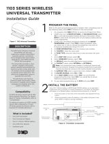
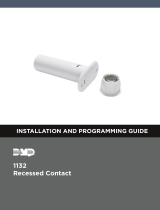
Internal Contact Magnetic Reed Switches
External Contact Terminal Block
Y2
U4
J4 Terminal
Block
Tamper
Switch
S1
J1
Antenna
Mounting
Block
J2
Battery
Mounting
Location
D1 LED and Lens
Antenna
Transmitter PCB
R14 Reed Switch
R7 Reed Switch
Mounting Hole
Transmitter Base
Red LED (Survey)
Figure 5: Internal and External Contact Points
Y2
U4
J4 Terminal
Block
S1
Tamper
Switch
J1
Antenna
Mounting
Block
J2
Battery
Mounting
Location
D1 LED and Lens
Antenna
Transmitter PCB
R14 Reed Switch
R7 Reed Switch
Magnet
Magnet
1101-WINT Universal
Transmitter
External
Contact
Magnet
External Contact
Terminal Block
Internal Contact
Reed Switches
Internal Contact
External Contact
Program External
Contact as next
consecutive Zone
Program Internal
Contact as one Zone
Window
Door
1101-WINT
Transmitter
Figure 6: External Contact Wiring

800-641-4282
www.dmp.com 2500 North Partnership Boulevard
LT-0694INT © 2015 Digital Monitoring Products, Inc.
15365
Battery Life Expectancy
Typical battery life expectancy for DMP Model 1101-WINT wireless transmitters is 5 years. DMP wireless equipment
uses two-way communication to extend battery life.
The following situations can reduce battery life expectancy:
• If a receiver is unplugged or not installed.
Note: Transmitters continue to send supervision messages until a receiver returns an acknowledgement.
After an hour the transmitter only attempts a supervision message every 60 minutes.
• Frequent transmissions, such as a door contact where messages are sent every time the door opens or closes.
• When installed in extreme hot or cold environments.
The following situation can extend battery life expectancy:
• Extend transmitter supervision time in panel programming.
• Infrequent transmission trips, such as a window that rarely sends messages.
Specications
Battery
Life Expectancy 5 years (normal operation)
Type 3.0V lithium CR123A
See Battery Life Expectancy for full details.
Frequency Range: 863-869 MHz
Dimensions
Transmitter Case 3.3” L x 1.6” W x 1.2” H
8.4 L x 4.06 W x 3.05 H cm
Transmitter Base 2.5” L x 1.3” W x 0.1” H
6.4 L x 3.3 W x 1.25 H cm
Magnet Housing 1.5” L x 0.5” W x 0.7” H
3.8 L x 1.3 W x 1.8 H cm
Magnet Spacer 1.5” L x 0.5” W x 0.1” H
3.8 L x 1.3 W x 0.25 H cm
Color White
Housing Material Flame retardant ABS
Compatibility
1100X-WINT Wireless Receiver
1100D-WINT Wireless Receiver
XT30INT Series panel
XR150INT/XR550INT Series panel
Patents
U. S. Patent No. 7,239,236
/