Page is loading ...

INSTALLATION GUIDE
1183-WINT Series Wireless Heat Detector
Description
The 1183INT Series wireless heat detectors are used with DMP 1100INT Series International Wireless Receivers. The
1183INT Series is available in two models: 1183INT-135F and 1183INT-135R.
The 1183INT-135F is a xed temperature detector that reacts to heat by responding to the xed 135° (57.2 C)
temperature setting. When activated, an alarm is sent to the control panel. The 1183INT-135F model has a black dot
on the heat collector n for identication.
The 1183INT-135R model is a combination rate-of-rise and xed temperature detector that detects heat quickly
by responding to a rapid temperature increase or a xed 135° (57.2 C) temperature setting. The element responds
to a rapid rise in temperature and sends an alarm to the control panel when the ceiling temperature increases
at a minimum rate of 15°F (-9.4 C) per minute.
An alarm is also sent to the panel if the ceiling
temperature reaches the xed 135° (57.2 C)
setting if the rate-of-rise is not exceeded.
Compatibility
1100INT Series International Wireless Receivers
What is Included
The 1183INT Wireless Heat Detector package
includes the following items:
• One 1183INT-135F Heat Detector with DMP
wireless transmitter installed
OR
• One 1183INT-135R Heat Detector with DMP
wireless transmitter installed
AND
• One 3V lithium CR123A battery
• Hardware pack
• Zone name and number label
• Serial number labels
Transmitter Serial Number
For your convenience, an additional pre-printed serial number label is included. Prior to installing the device, record
the serial number or place the pre-printed serial number label on the panel programming sheet. This number is
required during programming. As needed, use the zone name and number label to identify a specic transmitter.
Programming the Transmitter in the Panel
Locate and record the detector serial number. This number is required during programming. Program the device as a
FIRE type zone in Zone Information during panel programming. At the Serial Number: prompt, enter the eight-digit
serial number. Continue to program the zone as directed in the panel programming guide.
Note: When a receiver is installed, powered up, or the panel is reset, the supervision time for transmitters is reset.
If the receiver has been powered down for more than one hour, wireless transmitters may take up to an additional
hour to send a supervision message unless tripped, tampered, or powered up. This operation extends battery life for
transmitters. A missing message may display on the keypad until the transmitter sends a supervision message.
Transmitted Signal Outputs
The heat detector provides the signals listed in the table:
Signal Keypad Display
Alarm ALARM
Low battery LO BAT
Detector head removed TROUBLE
Heat Collector Fin
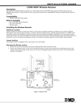
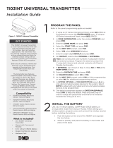
The 1183INT Series heat detectors use a heat collector n (See Figure 1) to detect temperature changes.
The n is spring loaded and sensitive to handling. Do not set the detector on the collector n
or put pressure on the n while handling as this could cause damage to the internal operation.
Figure 1: Heat Detector Exploded View
Detector Cap
Mounting Base
Alignment Notch
Tamper Post
Detector Cover
Battery Compartment
Heat
Collector
Fin

Digital Monitoring Products 1183INT Detector Installation Guide
2
Selecting the Proper Location
(LED Survey Operation)
For optimum wireless performance, install the transmitter away from large metal objects. Mounting the transmitter
on or near metal surfaces impairs performance. The 1183INT Series transmitters provide a survey capability to allow
one person to conrm transmitter communication with the receiver. The 1183INT transmitter PCB Red Survey LED
turns on whenever data is sent to the receiver then immediately turns off when the receiver acknowledgement is
received. The survey button is located within the battery compartment and the transmitter survey LED can be seen
near the survey button location. When the transmitter does not receive an acknowledgement from the receiver
the LED remains on for about 8 seconds to let you know communication is not established. Communication is also
faulty when the LED blinks multiple times in quick succession. Relocate the transmitter or receiver until the LED
immediately turns off indicating the transmitter and receiver are
communicating properly.
Test the communication between the control panel and the detector
before permanently mounting the detector as follows:
1. Program the transmitter into the panel. See Programming
Transmitter in the Panel. Install the battery.
Note: Survey operation requires that the detector have the mounting
base installed to engage the tamper switch.
2. Hold the detector up in the location where you plan to install it.
3. Press the survey button (See Figure 2) to send data to the
receiver to conrm operation.
General Location Guidelines
Use the following location guidelines to optimize performance and reduce the chance of false alarms from the
detector:
• Locate ceiling-mounted detectors in the center of a room or hallway at least 4 inches (10.2 cm) from any
walls or partitions
• Locate wall-mounted heat detectors so the top of the detector is 4 (10.2 cm) to 12 inches (30.5 cm) below
the ceiling
• Mount the detector on a rm permanent surface
• Locate the detector in environmentally controlled areas where the temperature does not exceed 100°F
(37.8°C).
• In rooms with sloped, peaked, or gabled ceilings, locate detectors 3 feet (.9 meters) down or away from the
highest point of the ceiling
• When mounting to suspended ceiling tile, the tile must be secured with the appropriate fastener to prevent
tile removal
Installing the Detector
Note: When setting up a wireless system, it is recommended
to program zones and connect the wireless receiver before
installing batteries in the transmitters.
Install the Mounting Base
1. Using the two screws provided, mount the base in the
location previously surveyed for proper communication.
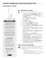
Attaching and Removing the Detector
1. Using the alignment notch on the lip of the mounting
base as a guide, align the detector with the alignment
tabs.
2. Insert the detector into the mounting base and turn
clockwise approximately 15 degrees. It should snap
rmly into place.
To remove the detector from the mounting base, grasp the
detector and turn it counterclockwise approximately 15
degrees. The detector should snap off of the mounting base.
See Figure 3.
Alignment
Tabs
Alignment
Tabs
Mounting Holes
Alignment Notch
Figure 3: Mounting Base
Figure 2: Survey Button
Survey
ButtonSurvey
LED
SURVEY

1183INT Detector Installation Guide Digital Monitoring Products
3
Installing or Replacing the Batteries
Observe polarity when installing the battery. Use only 3V lithium batteries, DMP Model CR123-FIRE or Panasonic
Model CR123A.
Note: When setting up a wireless system, it is
recommended to program zones and connect
the receiver before installing batteries in the
transmitters.
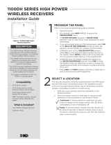
1. Slide the battery compartment cover away
from the detector to unsnap it and lift it off.
See Figure 4.
2. If replacing the battery, remove the old
battery and dispose of them properly.
3. Observing correct polarity, insert the new 3V
lithium battery into the battery compartment
and replace the cover. Use only new batteries
when replacing old ones.
4. Reattach the detector to the mounting base.
See Attaching and Removing the Detector.
5. Test the detector. See Testing the Detector.
Caution: Properly dispose of used batteries. Do not recharge, disassemble, heat above 212°F (100°C), or
incinerate. Risk of re, explosion, and burns.
Testing the Detector Alarm
1. To test the detector alarm, enable Walk Test operation on the control panel. If the system is monitored, the
system sends a System Test Begin report (System message S66) to the central station.
To conduct the Walk Test, reset the control panel by momentarily
placing a jumper on J16. From the keypad, enter the code 8144. The
keypad displays WALK TEST. Refer to the panel programming guide for
complete information on Walk Test operation.
2. For the XT30INT Series panels, select STD (Standard Walk Test). For the
XR150INT/XR550INT Series panels, select FI (Fire zones). A sensor reset
occurs after each detector tested.
3. Remove the heat detector from the mounting base. See Attaching and
Removing the Detector. Carefully short the two terminals (screw heads)
momentarily to send an alarm signal to the control panel. Verify that
the walk test trip counter increments to indicate a successful test. Once
testing is completed, install the detector back onto the mounting base.
Shorting the terminals does not affect the standard operation of the
detector.
4. Select END to stop the Walk Test. When the Walk Test ends or a
20-minute time-out expires, a nal Sensor Reset occurs. The System Test
End message (System message S67) is sent to the central station along
with verify and fail messages for each zone under test. Faulted zones
then display on the keypad.
Important: The control panel alarm and all auxiliary functions should be veried for a complete test of the system.
See the panel programming guide for additional information.
Battery Life Expectancy
Typical battery life expectancy for DMP wireless heat detectors is at least 2 years. DMP wireless equipment uses
two-way communication to extend battery life.
The following situations can reduce battery life expectancy:
• If a receiver is unplugged or not installed.
• Frequent transmissions, such as how often the detector is tested.
• When installed in extreme hot or cold environments.
Figure 4: Battery Compartment
Battery
Compartment
Battery Cover
Battery
Figure 5: Testing the Detector

LT-1186INT © 2016 Digital Monitoring Products, Inc.
800-641-4282
www.dmp.com
Designed, Engineered
and Assembled in U.S.A.
INTRUSION • FIRE • ACCESS • NETWORKS
2500 North Partnership Boulevard
Springfield, Missouri 65803-8877
16213
Specications
Battery
Life Expectancy 2 years
(normal operation)
3V Lithium CR123A
See Battery Life Expectancy for full details.
Low battery
Threshold signal 2.40V
Frequency Range 863-869 MHz
Dimensions
Detector 5.8” x 2.2”
(14.3cm x 6.1cm)
Heat alarm specications:
Rate-of-rise 15°F/min > 105°F
(8.3°C/min > 40.6°C)
Fixed 135°F ± 5°F
(57.2°C ± 2.8°C)
Color White
Patents
U. S. Patent No. 7,239,236
Compatibility
1100X-WINT Wireless Receiver
1100D-WINT Wireless Receiver
XT30INT Series panel
XR150INT/XR550INT Series panels
International Certications
EN 61000-6-3 EMC Generic Standards - Emission
standard for Residential, Commercial
and Light-industrial Environments
EN 50130-4 EMC Product Family Standard:
Immunity Requirements For
Components of Fire, Intruder and
Social Alarm Systems
/