Page is loading ...

INSTALLATION GUIDE
1141-WINT Wall Button
Description
The 1141-WINT Wall Button is a one-button wireless transmitter. The
1141-WINT may be used for a variety of applications such as Arming,
Disarming, turning an Output on or off, activating a Z-Wave Favorite,
or activating a Panic or Emergency alarm.
The 1141-WINT features a water-resistant button (when installed
using the double-sided tape mounting procedure) with a Status LED
to provide visual indication that a message has been transmitted and
received by the panel. The 1141-WINT operates using the supplied 3
Vdc Lithium batteries.
Compatibility
1100 Series International Wireless Receivers
What is Included
The 1141-WINT Wall Button includes the following:
• One 1141-WINT Wall Button Transmitter
• Two 3 Vdc Lithium CR2430 batteries
• Serial number label
Transmitter Serial Number
For your convenience, an additional pre-printed serial number label is included. Prior to installing the transmitter,
record the serial number or place the pre-printed serial number label on the 1141-WINT base (see Figure 4). This
number is required during programming. As needed, use the zone name and number label to identify a specic
transmitter.
Programming the Transmitter in the Panel
Refer to the panel programming guide as needed. Program the device as a zone in ZONE INFORMATION during
panel programming. At the Serial Number prompt, enter the eight-digit
serial number. Continue to program the zone as directed in the panel
programming guide.
Status LED Operation Programming
When the button is pressed, the 1141-WINT Status LED operates according
to the LED OPERATION NO YES option in ZONE INFORMATION.
YES - The Status LED blinks once when the button is pressed and then once
every second for ve minutes to conrm a message was sent.
NO - The Status LED blinks once when the button is pressed to conrm a message was sent.
When Supervision time is set to 0, the 1141-WINT Status LED blinks once every minute to conrm communication
from the panel. When Supervision time set to 60 or 240, the 1141-WINT Status LED only blinks when the button is
pressed.
Note: When a receiver is installed, powered up, or the panel is reset, the supervision time for transmitters is
reset. If the receiver has been powered down for more than one hour, wireless transmitters may take up to an
additional hour to send a supervision message unless tripped or powered up. This operation extends battery life for
transmitters. A missing message may display on the keypad until the transmitter sends a supervision message.
LED Survey
The 1141-WINT Transmitter provides a survey capability to allow one person to conrm transmitter communication
with the receiver. The 1141-WINT Transmitter Status LED turns on whenever data is sent to the receiver then
immediately turns off when the receiver acknowledgement is received.
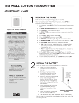
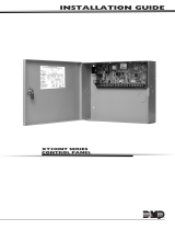
Figure 1: 1141-WINT Wall Button Transmitter
Water
Resistant
Button
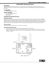
Figure 2: Status LED
LED

Digital Monitoring Products 1141-WINT Installation Guide
2
Pressing the button sends data to the receiver to conrm operation. When the transmitter does not receive
an acknowledgement from the receiver the LED remains on for approximately eight seconds to indicate that
communication is not established. Communication is also faulty when the LED ashes multiple times in quick
succession. Relocate the transmitter or receiver until the LED immediately turns off indicating the transmitter and
receiver are communicating properly. Proper communication between the transmitter and receiver is veried when
for each press of the button, the LED blinks immediately on and immediately off. Repeat this test to conrm ve
separate consecutive LED blinks. Any indication otherwise means proper communication has not been established.
Mounting the Transmitter
These instructions cover installing the 1141-WINT on an interior wall. Figures 3 and 4
show the base housing inside and outside views. For a water-resistant installation use
the double-sided tape mounting procedure.
Double-sided tape mounting
1. Install two 1/2” (12.7 mm) wide strips of double-sided tape (not included) in the
indentions on the back of the base housing.
2. Remove the backing from the tape and place the housing in the desired location
on the wall with the LED toward the top. See Figure 4.
Screw mounting
1. Insert a at screwdriver into the slot on the bottom of the 1141-WINT housing
and gently lift the screwdriver handle while pulling the halves apart.
See Figure 6.
2. Set aside the top housing containing the button and internal assembly.
3. Using two #6 Phillips head screws (not included), press through the depressions
and mount the base to the wall. See Figure 3.
4. Align the top housing with the base, keeping the LED toward the top, and snap
the top housing into place. See Figure 5.
Installing or Replacing the Batteries
Observe polarity when installing batteries. Use only 3 Vdc Lithium
batteries, DMP Model CR2430, or the equivalent battery from a local retail
outlet.
Note: When setting up a wireless system, it is recommended to program
zones and connect the receiver before installing batteries in the
transmitters.
1. Remove the top housing containing the button and internal
assembly. Insert a at screwdriver into the slot on the bottom of
the housing and gently lift the screwdriver handle while pulling the
halves apart. See Figure 6.
2. Using your hands, gently separate the top housing from the base.
3. Turn the top housing over and using your ngers, gently pull back
the top printed circuit board (PCB) snap. See Figure 7.
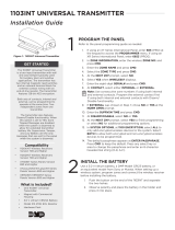
Figure 7: Top Housing PCB
Snaps Location
Top PCB
Snap
Bottom
PCB Snap
PCB
Supports
Top Housing Slot
Serial
Number
Label
1141-WINT Wall Button
Building Wall
Insert small
screwdriver and
lift to remove top
housing.
Do not twist.
Figure 6: Removing the
Top Housing
Figure 5: Installing the Top Housing
LED
Figure 4: Double-Sided Tape Mount
SERIAL #
Figure 3: Screw Mount

1141-WINT Installation Guide Digital Monitoring Products
3
4. Lean the PCB out and lift away from the bottom PCB snap. Do not
disassemble the button and gasket from the top housing.
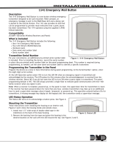
5. Remove the old batteries and dispose of properly. See Figure 8 for
battery location.
6. Observing polarity, place the 3.0 V lithium batteries in the holders
and press into place.
7. Re-insert the PCB into the bottom snap (serial number label near
bottom snap) and using your ngers, gently pull back the top snap
and press the PCB into place. Make sure the PCB is seated evenly
between the PCB supports.
8. Snap the top housing back on to the base with LED toward the top.
See Figure 5.
Caution: Properly dispose of used batteries. Do not recharge,
disassemble, heat above 212°F (100°C), or incinerate.
Risk of re, explosion, and burns.
Battery Life Expectancy
Typical battery life expectancy for DMP Model 1141-WINT wireless transmitters is 4 years. DMP wireless equipment
uses two-way communication to extend battery life.
The following situations can reduce battery life expectancy:
• If a receiver is unplugged, or not installed.
Note: Transmitters continue to send supervision messages until a receiver returns an acknowledgement.
After an hour the transmitter only attempts a supervision message every 60 minutes.
• When installed in extreme hot or cold environments.
The following situation can extend battery life expectancy:
• Extend or remove transmitter supervision time in panel programming.
Figure 8: PCB Battery Location

800-641-4282
INTRUSION • FIRE • ACCESS • NETWORKS
www.dmp.com 2500 North Partnership Boulevard
Designed, Engineered and
Assembled in U.S.A. Springeld, Missouri 65803-8877
LT-1326INT © 2016 Digital Monitoring Products, Inc.
16214
Specications
Battery
Life Expectancy 4 years (normal operation)
Type 3 Vdc Lithium CR2430
See Battery Life Expectancy for full details.
Frequency Range 863-869 MHz
Button Press
Time to Activate 1/8 sec. (.125 sec.)
Dimensions
Transmitter Case 3” H x 2-1/2” W x 1/2” D
Color White
Housing Material Flame retardant ABS
Patents
U. S. Patent No. 7,239,236
Compatibility
1100X-WINT Wireless Receiver
1100D-WINT Wireless Receiver
XT30INT Series panel
XR150INT/XR550INT Series panels
International Certications
EN 61000-6-3 EMC Generic Standards - Emission
standard for Residential, Commercial
and Light-industrial Environments
EN 50130-4 EMC Product Family Standard: Immunity
Requirements For Components of Fire,
Intruder and Social Alarm Systems
/