Page is loading ...

INSTALLATION GUIDE
XT30INT SERIES
CONTROL PANEL

Digital Monitoring Products XT30INT Series International Installation Guide
MODEL XT30INT CONTROL PANEL
INSTALLATION GUIDE
© 2018 Digital Monitoring Products, Inc.
Information furnished by DMP is believed to be accurate and reliable.
This information is subject to change without notice.

XT30INT Series Installation Guide Digital Monitoring Products
i
TABLE OF CONTENTS
Panel Specications .............................................................................. 1
1.1 Power Supply ..................................................................................................... 1
1.2 Communication ................................................................................................... 1
1.3 Panel Zones ........................................................................................................ 1
1.4 Keypads/Expansion ............................................................................................. 1
1.5 Number of Zones ................................................................................................ 1
1.6 Outputs .............................................................................................................. 1
1.7 EnclosureSpecications ...................................................................................... 1
Introduction .......................................................................................... 2
2.1 SystemCongurations ......................................................................................... 2
2.2 Caution Notes ..................................................................................................... 2
System Components ............................................................................. 3
3.1 WiringDiagram ................................................................................................... 3
3.2 LightningProtection ............................................................................................ 3
3.3 AccessoryDevices ............................................................................................... 3
3.4 XT30INTSeriesInternationalWiringDiagram ....................................................... 4
Installation ............................................................................................ 5
4.1 MountingtheEnclosure ....................................................................................... 5
4.2 MountingKeypads .............................................................................................. 6
4.3 InstallationSpecications .................................................................................... 6
Primary Power Supply ........................................................................... 6
5.1 AC terminals 1 and 2 ........................................................................................... 6
5.2 Transformer Types .............................................................................................. 6
5.3 PowerLED ......................................................................................................... 6
Secondary Power Supply ....................................................................... 7
6.1 Battery Terminals 3 and 4 .................................................................................... 7
6.2 EarthGround ...................................................................................................... 7
6.3 Replacement Period ............................................................................................ 7
6.4 Discharge/Recharge ............................................................................................ 7
6.5 BatterySupervision ............................................................................................. 7
6.6 XT30INT Power Requirements ............................................................................. 7
6.7 XT30INT Standby Battery Calculations .................................................................. 8
Bell Output ............................................................................................ 9
7.1 Terminals 5 and 6 ............................................................................................... 9
Keypad Data Bus ................................................................................... 9
8.1 Description ......................................................................................................... 9
8.2 Terminal7-RED................................................................................................. 9
8.3 Terminal 8 - YELLOW .......................................................................................... 9
8.4 Terminal9-GREEN ............................................................................................ 9
8.5 Terminal 10 - BLACK ........................................................................................... 9
8.6 KeypadBusLEDs ................................................................................................ 9
8.7 ProgrammingConnection .................................................................................... 9
8.8 KeypadAddressing .............................................................................................. 9
8.9 OvercurrentOVCLED .........................................................................................10
Smoke and Glassbreak Detector Output ............................................. 10
9.1 Terminal 11 .......................................................................................................10
Burglary Zones .................................................................................... 10
10.1 Description ........................................................................................................10
10.2 Operational Parameters ......................................................................................10
10.3 Zone Response Time ..........................................................................................11
10.4 KeyswitchArmingZone ......................................................................................11
Powered Zone for 2-Wire Smoke Detectors ........................................ 11
11.1 Terminals 25 and 26 ...........................................................................................11

Digital Monitoring Products XT30INT Series Installation Guide
ii
TABLE OF CONTENTS
Annunciator Outputs ........................................................................... 11
12.1 Description ........................................................................................................11
12.2 HarnessWiring ..................................................................................................11
12.3 Model 860 Relay Module .....................................................................................11
PHONE LINE RJ Connector .................................................................. 12
13.1 Description ........................................................................................................12
ETHERNET Connector .......................................................................... 12
14.1 Description ........................................................................................................12
14.2 ETHERNETLEDs ................................................................................................12
RESET Header ...................................................................................... 13
15.1 Description ........................................................................................................13
Flash LOAD Jumper ............................................................................. 14
16.1 Description ........................................................................................................14
Cellular Connections ........................................................................... 14
17.1 Cellular .............................................................................................................14
Troubleshooting .................................................................................. 15
18.1 TroubleshootingSection .....................................................................................15
18.2 CommonLCDKeypadDisplays ............................................................................15

XT30INT Series Installation Guide Digital Monitoring Products
1
PANEL SPECIFICATIONS
Panel Specications
1.1 Power Supply
Transformer Input: Wire-in — Model 320INT, 16 VAC, 43 VA, Primary input: 230 VAC, 50 Hz
Panel Current Draw: 400 mA AC
Standby Battery: 12 VDC, 1.0 Amps Max. charging current
Models 365, 366, 368, or 369
Replace every 3 to 5 years
Auxiliary Output: 12 VDC at 500 mA
Bell Output: 12 VDC at 1.5 Amps
Smoke Detector Output: 12 VDC at 100 mA
All circuits inherent power limited
Note: Please see the Listed Compliance Specications section for certicated application requirements.
1.2 Communication
Built-in SDLC Digital Dialer communication to DMP Model SCS-1R Receivers
Built-in network communication to DMP Model SCS-1R or SCS-VR Receivers
Built-in or modular cellular communication to DMP Model SCS-1R or SCS-VR Receivers
Built-in CID (Contact ID) dialer communication to DMP Model SCS-1R Receivers
1.3 Panel Zones
Nine 1k Ohm EOL burglary zones: zones 1 to 9
One 3.3k Ohm EOL Class B powered re zone with reset capability: zone 10
1.4 Keypads/Expansion
Connect up to eight supervised alphanumeric keypads per panel, four of which can be wireless keypads.
In addition, the following zone expanders can be added:
• One, eight, and 16-zone expansion modules
• Single-zone PIR and glassbreak detectors
1.5 Number of Zones
• Onboard zones 1-10
• Eight keypad bus addresses with zones 11-14, 21-24, 31-34, 41-44, 51-54, 61-64, 71-74, and 81-84
• Zone numbers 31 to 34 and 41 to 44 can support 1100 Series Key Fobs or DMP wireless output modules
• XT50INT has 16 additional onboard wireless zones numbered 80, 85-99
1.6 Outputs
The XT30INT panels provide four open collector outputs rated for 50 mA each. A Model 300 Output Harness is
required. The open collector outputs provide the ground connection for a positive voltage source.
1.7 Enclosure Specications
The XT30INT panels ship standard in a 340INT enclosure with EOL resistors, battery leads, user’s guide, and
programming sheet.
Enclosure Model Size Color Construction (Cold Rolled Steel)
340INT 31.75 W x 24.13 H x 19.685 D cm Gray (G) 20-Gauge
349INT 31.75 W x 29.21 H x 8.89 D cm Gray (G) 20-Gauge
349AINT 33.25 W x 29.59 H x 9.14 D cm Gray (G) 18-Gauge with 16-Gauge door

Digital Monitoring Products XT30INT Series Installation Guide
2
INTRODUCTION
Introduction
2.1 System Congurations
The panel can be programmed to operate as any of the following system types:
• All/Perimeter system that provides one perimeter area and one interior area
• Home/Sleep/Away system that provides one perimeter, one interior, and one bedroom area. The
bedroom area provides for any protection devices the user wants disarmed during their sleeping hours
and armed in the Away mode.
• Six area system that provides areas of protection that can be independently armed or disarmed.
2.2 Caution Notes
Throughout this guide you will see caution notes containing information you need to know when installing
the panel. These cautions are indicated with a yield sign. Whenever you see a caution note, make sure you
completely read and understand its information. Failing to follow the caution note can cause damage to the
equipment or improper operation of one or more components in the system. See the example shown below.
Always ground the panel before applying power to any devices: The panel must be properly grounded
before connecting any devices or applying power to the panel. Proper grounding protects against
Electrostatic Discharge (ESD) that can damage system components.
Remove All Power From the Panel! Remove all AC and Battery power from the panel before installing or
connecting any modules, cards, or wires to the panel.

XT30INT Series Installation Guide Digital Monitoring Products
3
SYSTEM COMPONENTS
System Components
3.1 Wiring Diagram
The system wiring diagram in Figure 1 shows some of the accessory devices for use in various applications.
A description of each module follows.
3.2 Lightning Protection
Metal Oxide Varistors and Transient Voltage Suppressors help protect against voltage surges on input and
output circuits. This transient protection provides additional resistance to electrical surges such as lighting.
3.3 Accessory Devices
Cellular Communicator Cards
263HINT HSPA + Cellular
Communicator Card
Allows you to connect the XT30INT Series to any compatible HSPA+/SMS network.
Zone and Output Expansion Modules
710 Bus Splitter/Repeater Increases keypad wiring distance to 2500 feet.
714-8INT, 714-16INT Zone Expander
Provides Class B zones for burglary and non-powered re devices.
712-8INT Zone Expander Provides 8 zones for burglary devices.
860INT Relay Output Module Provides one relay and three relay sockets for expansion of up to four relays.
DMP Two-Way Wireless Devices
1100DINT Receiver Supports transmitters in residential or commercial wireless operation on the keypad buss.
1100RINT Repeater Provides additional range for wireless devices
1101INT Universal Transmitter Provides both internal and external contacts that may be used at the same time to yield two
individual reporting zones from one wireless transmitter.
1103INT Universal Transmitter
Provides bothinternalandexternalcontactsthatmaybeusedatthesametimetoyieldtwo
individualreportingzonesfromonewirelesstransmitter.RequiresEOLresistorforexternal
contact. Provides Disarm/Disable functionality.
1106INT Universal Transmitter Provides both internal and external contacts that may be used at the same time to yield two
individual reporting zones from one wireless transmitter.
1107INT Micro Window
Transmitter
Provides a window transmitter and magnet.
1142BC-INT Two-button Panic
Belt Clip Transmitter
Provides portable two-button panic operation.
1142INT Two-button Panic
Transmitter
Provides permanently mounted under-the-counter two-counter two-button panic operation.
1144-4INT (Four-Button)
1144-2INT (Two-Button)
1144-1INT (One-Button)
Key Fob transmitters designed to clip onto a key ring or lanyard.
1121INT PIR Motion Detector Provides motion detection with pet immunity.
1126RINT PIR Motion Detector Ceiling mount motion detector with panel programmable sensitivity and Disarm/Disable
functionality.
1127CINT/1127WINT PIR Motion
Detector
Wall mount motion detector with panel programmable sensitivity and Disarm/Disable
functionality.
1129INT Glassbreak Detector Detects the shattering of framed glass mounted in an outside wall and provides full-pattern
coverage and false-alarm immunity.
1131INT Recessed Contact
Provides concealed protection for doors, windows or other applications.
734INT Wiegand Interface Module Provides arming, disarming, and codeless entry using access control readers.
1135INT Siren Provides a wireless siren.
1139INT Bill Trap Provides a silent alarm option for retail and banking cash drawers.
Keypads
LCD keypads Allows you to control the panel from various remote locations. Connect up to eight keypads.
Model 7060-WINT, 7063-WINT, 7073-WINT Thinline™ keypads,
and 7872INT and 7873INT
Graphic Touchscreen keypads to the keypad bus using terminals 7, 8, 9, and 10.

Digital Monitoring Products XT30INT Series Installation Guide
4
SYSTEM COMPONENTS
3.4 XT30INT Series International Wiring Diagram
50mV
24.13W x 10.5H cm

XT30INT Series Installation Guide Digital Monitoring Products
5
SYSTEM COMPONENTS
Installation
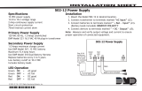
4.1 Mounting the Enclosure
The metal enclosure must be mounted in a secure, dry place to protect the panel from damage due to
tampering or the elements. It is not necessary to remove the PCB when installing the enclosure. The PCB
may be installed in the standard 340INT Small enclosure, optional 349INT Medium enclosure, or the optional
349AINT Attack enclosure.
The 349AINT Attack Resistant enclosure is factory shipped with one knockout on the top left of the
enclosure. As needed, additional knockouts may be added at the time of installation. See Figure 3 for the
positions on the enclosure that can be added. Each additional knockout must be lled with conduit.
Dual 1/2" and 3/4" Conduit Knockout
Battery Shel
f
Enclosure Mounting Hole
s
Slide panel PCB into lower enclosure slots
Panel
PCB
screw
Model 349INT Enclosure
Slide panel PCB between formed metal supports
Dual 1/2" and 3/4" Conduit Knockouts
Battery Shelf
Enclosure Mounting Holes
Enclosure
Mounting
Hole
Enclosure
Mounting
Hole
Panel
PCB
screw
Model 340INT Enclosure
J3
Phone
Line
Outputs
J11
1
2
3
4
J1
Ethernet
J16
Reset
J7 RJ
Supervision
J24
Celllular
header
connection
Panel
PCB
screw
Panel
PCB
screw
Enclosure
Mounting
Hole
J3
Phone
Line
Outputs
J11
J1
Ethernet
J16
Reset
J7 RJ
Supervision
J24
Celllular
header
connection
1
2
3
4
J18
Load
RED
Programming
J8
J18
Load
RED
Programming
J8
Tamper Switch
for 349INT
Enclosure
Tamper Switch
for 340INT
Enclosure
Figure 2: Standard 340INT Enclosure (left), Optional 349INT Enclosure (right)
3-Hole
Pattern for
Accessory
Modules
* 349AINT Optional Knockout
Dual 1 3/4" and 1 3/8" Conduit Knockouts
Battery Shelf
*
*
*
*
*
Model 349AINT Enclosure
Tamper Switch
for 349AINT
Attack
Resistant
Enclosure
Slide panel PCB between formed metal supports
J3
Phone
Line
Outputs
J11
1
2
3
4
J1
Ethernet
J16
Reset
J7 RJ
Supervision
J24
Celllular
header
connection
J18
Load
RED
Programming
J8
Figure 3: Optional 349AINT Enclosure

Digital Monitoring Products XT30INT Series Installation Guide
6
INSTALLATION
4.2 Mounting Keypads
DMP keypads have removable covers that allow the base to be mounted on a wall or other at surface
using the screw holes provided on each corner.
4.3 Installation Specications
Several factors determine the performance characteristics of the keypad bus: the length of wire used, the
number of devices connected, and the voltage at each device. When planning a keypad bus installation,
keep in mind the following four specications:
1. DMP recommends using 18 or 22-gauge unshielded wire for all keypad circuits. Do not use twisted
pair or shielded wire for keypad bus data circuits.
2. On keypad bus circuits, to maintain auxiliary power integrity when using 22-gauge wire do not exceed
500 feet. When using 18-gauge wire do not exceed 1,000 feet. To increase the wire length or to add
devices, install an additional power supply.
Note: Each panel allows a specic number of supervised keypads. Add additional keypads in the
unsupervised mode. Refer to the panel installation guide for the specic number of supervised
keypads allowed.
3. Maximum distance for any one bus circuit (length of wire) is 2,500 feet regardless of the wire gauge.
This distance can be in the form of one long wire run or multiple branches with all wiring totaling no
more than 2,500 feet. As wire distance from the panel increases, DC voltage on the wire decreases.
4. Maximum voltage drop between the panel (or auxiliary power supply) and any device is 2.0 VDC. If
the voltage at any device is less than the required level, add an auxiliary power supply at the end of
the circuit. When voltage is too low, the devices cannot operate properly.
For additional information refer to the 710 Installation Sheet (LT-0310) and or the LX-Bus/Keypad Bus
Wiring Application Note (LT-2031).
Primary Power Supply
5.1 AC terminals 1 and 2
Connect the transformer wires to terminals 1 and 2 on the panel. Use no more than 70 ft. of 16 gauge, or
40 ft. of 18 gauge, wire between the transformer and the panel to deliver a minimum of 15.5 VAC when
500mA of current draw is used from the auxiliary power supply terminal 7.
Always ground the panel before applying power to any devices: The panel must be properly grounded
before connecting any devices or applying power to the panel. Proper grounding protects against
Electrostatic Discharge (ESD) that can damage system components. See Earth ground, in the Secondary
Power Supply section.
5.2 Transformer Types
The transformer for the panel is 16 VAC 43 VA, which provides up to 1.5 Amps of bell output current,
500mA of auxiliary current, and 100mA of smoke detector output. Use the Model 320INT wire-
in transformer with the panel. The total current available is limited by the total battery standby
requirements of the installation.
The transformer must be connected to a 230 VAC 50 Hz commercial power outlet that is not con trolled by
a wall switch. Never share the transformer output with any other equipment.
5.3 Power LED
When either AC transformer power or DC battery power is connected to the panel the PWR LED shows
steady green.

XT30INT Series Installation Guide Digital Monitoring Products
7
INSTALLATION
Secondary Power Supply
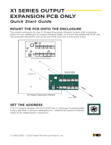
6.1 Battery Terminals 3 and 4
Connect the black battery lead to the
negative battery terminal. The negative
terminal connects to the enclosure
ground internally through the XT30INT
circuit board. Connect the red battery
lead to the positive battery terminal.
Observe polarity when connecting the
battery.
Add a second battery in parallel
using the DMP Model 318 Dual Battery
Harness. DMP requires each battery
be separated by a PTC in the battery
harness wiring to protect each battery
from a reversal or short within the
circuit. See Figure 4.
Use sealed lead-acid batteries only:
Use 12 VDC sealed lead-acid rechargeable battery. Batteries supplied by DMP have been tested to ensure
proper charging with DMP products.
GEL CELL BATTERIES CANNOT BE USED WITH THE XT30INT SERIES INTERNATIONAL PANEL.
6.2 Earth Ground
Terminal 4 of the panel must be connected to earth ground using 14 gauge or larger wire to provide proper
transient suppression. DMP recommends connecting to a metal cold water pipe or ground rod only. Do not
connect to electrical conduit or a telephone company ground.
6.3 Replacement Period
DMP recommends replacing the battery every 3 to 5 years under normal use.
6.4 Discharge/Recharge
The panel battery charging circuit oat charges at 13.8 VDC at a maximum current of 1.5 Amps using a 43 VA
transformer. The total current available is reduced by the combined auxiliary current draw from terminals 7,
11, and 25. The various battery voltage levels are listed below:
Battery Trouble: Below 11.9 VDC
Battery Restored: Above 12.6 VDC
6.5 Battery Supervision
The panel tests the battery once every hour when AC power is present. This test occurs 15 minutes past
each hour and lasts for ve seconds. A load is placed on the battery and if its voltage falls below 11.9 VDC a
low battery is detected. If AC power has failed, a low battery is detected any time the battery voltage falls
below 11.9 VDC.
If a low battery is detected with AC power present, the test is repeated every two minutes until the battery
charges above 12.6VDC; the battery restored voltage. If a faulty battery is replaced with a fully charged
battery, the restored battery will not be detected until the next two-minute test is done.
6.6 XT30INT Power Requirements
During AC power failure, the panel and all auxiliary devices connected draw their power from the battery.
All devices must be taken into consideration when calculating the battery standby capacity. On the following
page is a list of the power requirements of the panel. Add the additional current draw of DMP keypads,
smoke detector output, and any other auxiliary devices used in the system for the total current required.
The total is then multiplied by the total number of standby hours required to arrive at the total Ampere-
hours required.
AC
1 2 3 4
+BAC –B
318 Battery
Harness
Panel Red and
Black Battery Cables
Red
Black
Battery
Battery
Red
Black
5 6
BELL GND
To AC
14 AWG to
Earth Ground
XT30INT
Panel
PTC
To Bell
Circuit
Figure 4: Wiring Multiple Batteries

Digital Monitoring Products XT30INT Series Installation Guide
8
INSTALLATION
6.7 XT30INT Standby Battery Calculations
Standby Battery Power Calculations Alarm Current
XT30INT International Panel
Built-in Network (additional current)
ActiveZones1-9
ActiveZone10
2-WireSmokeDetectors
Panel Bell Output
x
x
x
x
x
205mA
145mA
1.6mA
4mA
0.1mA
______mA
______
______
______
______
Qty ______
Qty ______
Qty ______
1500mA
x
x
x
x
205mA
145mA
*2mA
30mA
0.1mA
Max.
______mA
______
______
______
______
______
263HINT HSPA+ Cellular Communicator x 24mA ______ Qty ______ x 28mA ______
1100DINTInternationalWirelessReceiver x 40mA ______ Qty ______ x 40mA ______
860RelayOutputModule(onerelayactive)
Allfourrelaysactive
x 34mA
138mA
______
______
Qty _______ x 34mA
138mA
______
______
7060-WINT/7063-WINTInternationalThinline
Keypad
x 72mA ______ Qty ______ x 87mA ______
7073-WINTInternationalThinlineKeypadActive
Zones (EOL Installed)
x 85mA
1.6mA
______
______
7872-WINTGraphicTouchscreenKeypad
ActiveZones(EOLInstalled)
x 145mA
1.6mA
______
______
Qty ______
Qty ______
x
x
215mA
2.0mA
______
______
7873-WINTGraphicTouchscreenKeypad
ActiveZones(EOLInstalled)
x
x
143mA
1.6mA
______
______
Qty ______
Qty ______
x
x
243mA
*2mA
______
______
712-8INT Zone Expansion Module
ActiveZones(EOLInstalled)
x
x
17mA
1.6mA
______
______
Qty ______
Qty ______
x
x
17mA
*2mA
______
______
714-8INT, 714-16INT Zone Expansion Module
ActiveZones(EOLInstalled)
x
x
20mA
1.6mA
______
______
Qty ______
Qty ______
x
x
20mA
1.6mA
______
______
734INTWiegandInterfaceModule
ActiveZones(EOLInstalled)
x 15mA
1.6mA
______
______
Qty ______
Qty ______
x
x
15mA
*2mA
______
______
Aux.PoweredDevicesonTerminals7and11
OtherthanKeypadsandModules
x ______mA ______mA
Total Standby
Total Standby______mA x number of Standby Hours
needed
Total Alarm
*Basedon10%ofactivezonesinalarmcondition.
______mA
______ =
______mA
+
Total
Total Alarm
________mA-hours
________mA-hours
________mA-hours
X .001
=________Amp-hrs
______mA
Required

XT30INT Series Installation Guide Digital Monitoring Products
9
INSTALLATION
Bell Output
7.1 Terminals 5 and 6
Nominal 12 VDC is supplied by terminal 5 on the panel to power alarm bells or horns. The output is rated
for a maximum of 1.5 Amps with a 40 VA transformer. This output can be steady, pulsed, or Temporal Code
3 depending upon the Bell Action specied in Bell Options programming. Terminal 6 is the ground reference
for the bell circuit. If using a horn or siren, a 1k 0hm resister should be added across the bell circuit for
supervision.
Keypad Data Bus
8.1 Description
Terminals 7, 8, 9, and 10 of the panel are designated as the keypad data bus. In addition to keypads, the
XT30INT International allows the connection of any combination of zone expansion modules, Glassbreak
Detectors, and PIRs to the keypad bus up to the maximum of eight devices.
8.2 Terminal 7 - RED
Nominal 12 VDC is supplied at terminal 7 to power keypads and zone expanders. This is also where power
for any auxiliary device is supplied. The ground reference for terminal 7 is terminal 10. The maximum output
is rated at 500mA. All auxiliary devices totaled together must not exceed the Terminal 7 maximum current
rating of 500mA. When the number of keypads or other expansion devices attached exceeds the amount of
output current available, attach an external power supply as dened in the Model 710 Installation Sheet
(LT-0310).
8.3 Terminal 8 - YELLOW
Data receive from keypads and zone expanders.
8.4 Terminal 9 - GREEN
Data transmit to keypads and zone expanders.
8.5 Terminal 10 - BLACK
Terminal 10 is the ground reference for LCD keypads, zone expanders, and any auxiliary devices being
powered by terminals 7 and 11.
8.6 Keypad Bus LEDs
The two LEDs located just above terminal 13 indicate keypad transmit data (XMIT) and keypad receive data
(RCV). The bottom LED ashes green to indicate data being transmitted from the panel. The top LED ashes
yellow to indicate data being received by the panel from keypads, zone expanders, etc.
8.7 Programming Connection
A locking 4-pin PROG header is provided to connect a keypad when using a DMP Model 330 Programming
Cable. This provides a quick and easy connection for programming the panel.
8.8 Keypad Addressing
Keypad Bus expansion zones are numbered in groups of four corresponding to the address. Example: address
1 is zones 11-14 and address 5 is zones 51-54. There are a maximum of 32 zones possible on the Keypad Bus.
All keypad zones terminate with a 1k 0hm EOL resister.
Address XT30INT
International
Zone Number
1 11-14
2 21-24
3 31-34
4 41-44
5 51-54
6 61-64
7 71-74
8 81-84

Digital Monitoring Products XT30INT Series Installation Guide
10
INSTALLATION
8.9 Overcurrent OVC LED
The Overcurrent LED (OVC) lights Red when the devices
connected to the Keypad Bus draw more current than the
auxiliary output rating. The OVC LED is located above
terminals 9 and 10 as shown in Figure 4. When the OVC LED
lights Red, the Keypad bus/auxiliary power (terminal 7) and
the PROG header shut down.
Smoke and Glassbreak Detector Output
9.1 Terminal 11
Nominal 12VDC at 100mA maximum (shared by terminal 25) is
supplied at terminal 11 to power 4-wire smoke detectors or
other auxiliary powered devices. This output can be turned
o by the user for 5 seconds using the Sensor Reset option
in the User Menu. Terminal 10 is the ground reference for
terminal 11.
Burglary Zones
10.1 Description
On XT30INT panels, terminals 12 to 24 are the nine burglary zones. For programming purposes, the zone
numbers are 1 to 9. The zone congurations on terminals 12 to 24 are described below.
Terminal Function Terminal Function
12 Zone 1 voltage sensing 19 Ground for zones 5 & 6
13 Ground for zones 1 & 2 20 Zone 6 voltage sensing
14 Zone 2 voltage sensing 21 Zone 7 voltage sensing
15 Zone 3 voltage sensing 22 Ground for zones 7, 8, & 9
16 Ground for zones 3 & 4 23 Zone 8 voltage sensing
17 Zone 4 voltage sensing 24 Zone 9 voltage sensing
18 Zone 5 voltage sensing
The voltage sensing terminal measures the voltage across the 1k Ohm End-of-Line resistor and the zone’s
ground terminal. Dry contact sensing devices can be used in series (normally-closed) or in parallel (normally-
open) with any of the burglary protection zones.
10.2 Operational Parameters
Each burglary protection zone detects four conditions: tamper, open, normal, and short.
The parameters for each are listed below:
Condition Resistance on Zone Voltage on Zone Terminal
Tamper over 2.43k ohms > 2.9 VDC
Open 1430 Ohms to 2,430 Ohms 2 - 2.9 VDC
Normal 215 to 1430 Ohms 1.2 to 2.0 VDC
Short under 215 Ohms under 1.2 VDC
J3
Phone Line
J7 RJ
Supervision
OVC LED
Power
LED
Figure 5: OVC LED location
1K Ohm
1K Ohm
R2
R1
Dual 1K Ohm
Normally Closed
1K Ohm
1K Ohm
R2
R1
1K Ohm
1K Ohm
R2
R1
Dual 1K Ohm
Normally Open
Dual 1K Ohm
Combination Normally
Open and Normally Closed
Door Door Door
Tamper
Figure 6: Protection Zone Contact Wiring

XT30INT Series Installation Guide Digital Monitoring Products
11
INSTALLATION
10.3 Zone Response Time
A condition must be present on a zone for 500 milliseconds before it is detected by the panel. Ensure
detection devices used on the protec tion zones are rated for use with this delay.
10.4 Keyswitch Arming Zone
You can use a momentary keyswitch on a zone programmed as an Arming type for use in arming and
disarming the system without a code.
Powered Zone for 2-Wire Smoke Detectors
11.1 Terminals 25 and 26
A resettable 2-wire Class B powered zone is provided on terminals 25 (positive) and 26 (negative) of the
panel. For programming purposes, the zone number is 10 on the XT30INT International. The zone uses a
Model 309, 3.3k Ohm EOL resistor (provided with the panel) and has an operating range of 8.8 to 13.9 VDC.
The compatibility identier is: B
Caution: Sensor reset on zone 10 drops power to devices on this zone, causing the panel to sense an open
condition on all zone types other than Fire, Fire Verify, and Supervisory. Whenever non-Fire and non-
Supervisory zone types are used on zone 10, make the appropriate adjustments to the zone’s Armed Action
to prevent false alarms from occurring.
Annunciator Outputs
12.1 Description
The four annunciator outputs can be programmed to indicate the activity of the panel’s zones or conditions
occurring on the system. Annunciator outputs do not provide a voltage but instead switch-to-ground voltage
from another source. The outputs can respond to any of the conditions listed below:
1) Activation by zone condition: Steady, Pulse, Momentary, or Follower 6) Ambush alarm
2) Manually from the keypad 7) Exit and Entry timers
3) Communication failure 8) System Ready
4) Armed area annunciation 9) Late to Close
5) Fire Alarm or Fire Trouble
12.2 Harness Wiring
The open collector outputs are accessible by installing the DMP 300 Harness on the 4-pin OUTPUTS header.
The output locations are shown below. For listed applications, devices connected to outputs must be located
within the same room as the panel.
Output Color Wire Output Color Wire
1 Red 1 3 Green 3
2 Yellow 2 4 Black 4
12.3 Model 860 Relay Module
Connect a Model 860 Relay Module to the panel to provide relays for the annunciator outputs that can be
used for electrical isolation between the alarm panel and other systems or for switching voltage to control
various functions. The module includes one relay and provides three additional sockets for expansion of up
to four relays. Power is supplied to the relay coils from the panel keypad bus. The 860 mounts inside the
panel enclosure using the 3-hole mounting conguration. Plastic standos are provided with the module for
ease of installation. A 4-wire harness is also provided that connects the Model 860 to the panel.
Relay Contact Rating: 1 Amp at 30 VDC

Digital Monitoring Products XT30INT Series Installation Guide
12
INSTALLATION
PHONE LINE RJ Connector
13.1 Description
Connect the panel to the public telephone network by installing a DMP 356 RJ Cable between the panel’s
PHONE LINE connector and the RJ31X or RJ38X phone jack.
A two pin RJ SUP header is provided to allow monitoring of the telephone cable connected between the
panel and a RJ38X jack (pins 2 and 7 jumpered). Attach a DMP Model 306 Harness between RJ SUP and any
available zone. The RJ SUP pins are connected via the telephone cable to the RJ38X jack pins 2 and 7. The
RJ38X jack provides a jumper between pins 2 and 7 which completes the circuit. Program the zone as a
Supervisory type (SV). When the telephone cable is removed, the keypad displays zone trouble and produces
a steady tone.
To Telephone
Line
RJ31X or RJ38X
Phone Block
8
7
6
54
3
2
1
Ring Tip
To Premise
Phone(s)
Ring 1
Tip 1
Figure 7: Phone Jack Wiring
ETHERNET Connector
14.1 Description
The ETHERNET Connector is available on the Network version and connects directly to an Ethernet network
using a standard patch cable.
14.2 ETHERNET LEDs
The two LEDs, located on the left side of the ETHERNET Connector, indicate network operation. The top,
Link LED is a steady green light when an ethernet cable is connected. The bottom, Activity LED ashes
yellow to indicate messages are being received or transmitted.

XT30INT Series Installation Guide Digital Monitoring Products
13
INSTALLATION
RESET Header
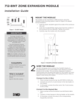
15.1 Description
The RESET header is located just above the terminal strip on the right side of the circuit board and is used
to reset the XT30INT Series International microprocessor. To reset the panel when rst installing the system,
install the reset jumper before applying power to the panel. After connecting the AC and battery, remove
the reset jumper.
To reset the panel while the system is operational, for example, prior to reprogramming, install the reset
jumper without powering down the system. Remove the reset jumper after one or two seconds.
After resetting the panel, begin programming within 30 minutes. If you wait longer than 30 minutes, reset
the panel again.
XT30INT Panel
PHONE LINE
OUTPUTS
J11
1
2
3
4
RJ
Supervision
CELL MODULE
Momentarily place
the Reset jumper
over both of the
RESET pins to
reset the panel.
J16
RESET
J18
LOAD
ETHERNET
OVC LED
Power
LED
PROG
J8
XMIT
RCV
J24
J1
J7
J3
Figure 8: Panel Showing the RESET Header

Digital Monitoring Products XT30INT Series Installation Guide
14
INSTALLATION
Flash LOAD Jumper
16.1 Description
The XT30INT Series panel software can be updated via the panel’s programming (PROG) header. To update
the panel with a new software version, complete the following steps at the protected premise:
1. Place a jumper across the RESET header and then remove the yellow and green wires from keypad bus
terminals 8 and 9.
2. Connect a DMP 399 Cable from the PROG Header to the serial port of your PC operating Remote Link
and containing the XT RU le. Requires Remote Link 1.43 or higher.
3. Start Remote Link and create or open the XT Series control panel account that matches the panel to be
updated.
4. Set the Connection Information Type to Direct with a baud rate of 38400 and choose the appropriate
COM port.
5. Select Panel>Remote Update, then select the correct RU le for the XT panel model.
6. While placing a short across the LOAD header, remove the jumper from the RESET header. Click
<Update> in Remote Link.
7. After the software version is updated, remove the short from the LOAD header. Place the jumper across
RESET then remove the 399 cable.
8. Replace the yellow and green wires to terminals 8 and 9.
9. Remove RESET jumper to resume normal panel operation.
Cellular Connections
17.1 Cellular
The CELL MODULE header is provided to connect a 263HINT HSPA+ Cellular Communicator. The cellular
antenna connection protrudes through the top of the enclosure.
Note: DO NOT MISALIGN THE CELL MODULE 12 PIN CONNECTOR ONTO CELL MODULE HEADER. If needed,
the PCB can be removed from the enclosure to allow placement of the cell module.
Outputs
J11
1
2
3
4
J16
Reset
Brass
Washer
J18
Load
J1
Ethernet
Programming
J8
XMIT
RCV
263HINT
Cellular
Communicator
Figure 9: Cellular Antenna Connections

XT30INT Series Installation Guide Digital Monitoring Products
15
INSTALLATION
Troubleshooting
18.1 Troubleshooting Section
This section provides troubleshooting information for use when installing or servicing an XT30INT system.
Problem Possible Cause Possible Solutions
Keypad displays “SYSTEM TROUBLE”
RESET Jumper is installed. RemovetheRESETjumper.
Openorshortonthegreendatawireto
thekeypad.
Checkforbrokenorshortedwiresbetween
thepanelandthekeypad.
Badkeypadorzoneexpanderisaecting
theGreendatawire.
Replacekeypadorzoneexpander.
Keypad keyboard is not functional.
Whenakeyispressed,onlyashort
beep is emitted.
Openorshortontheyellowdatawireto
thekeypad.
Checkforbrokenorshortedwiresbetween
thepanelandthekeypad.
Badkeypadorzoneexpander.isaecting
theYellowdatawire.
Replacekeypadorzoneexpander.
KeypadXMITGreenLEDiso
Panel is reset. RemoveRESETjumper.
FlashLoadenabled. RemoveLOADjumperandresetpanel.
KeypadRCVYellowLEDiso
Keypad/expanders are not connected to panel.
Connect keypad/expanders.
Keypad/expandersaregreaterthanve. Checkkeypad/expandersaddress.
Keypadbeepswhenkeysarepressed,
butwillnotallowtheusertoarmor
disarm,orentertheUserMenu.
Twoormorekeypadsareassignedtothe
same address.
Seteachkeypadonthesystemtoaunique
address.
PowerLEDiso. AC/Battery is not connected. Connect AC power and/or battery.
OvercurrentOVCLEDturnsRed Toomanydevicesattachedtoauxiliary. Maximum current draw is 500 mA.
WirelessGreenTXLEDiso. WirelessHouseCodeisnotprogrammed. ProgramHouseCodeinSystemOptions.
Keypad operates intermittently,
keystrokes may be missed, or display
does not update consistently.
Wirelengthmayexceedmaximum,
resultinginpoordataperformance.
Wirelengthcanbereducedoraheavier
gaugeused.
Apowersupplycanbeaddednearthekeypad.
See LT-2031, LX-Bus/Keypad Bus Wiring
Application Note for more information.
18.2 Common LCD Keypad Displays
Listed below are several keypad messages you may see on the display. Follow the instructions in the Possible
Solutions column to correct the problem.
Message Meaning Possible Solutions
INVALIDCODE
Theusercodeenteredisnotrecognizedbythesystem.
Checktheusercodeandtryagain.
CLOSINGTIME
Thesystemwasnotarmedatitsscheduledclosing
time.
Usersstillonthepremiseshouldarmthesystemor
extendthescheduletoalatertime.
AC TROUBLE ThesystemACislowormissing.
CheckthattheACconnectionsaregoodfromthe
transformer.
BATTERY TROUBLE TheSystembatteryiseitherlowormissing.
Checktoseethatbatteryandconnectionsaregood.
SYSTEM BUSY
Thesystemisperforminganothertaskwitha
higherpriorityorisbeingRemoteProgrammed.
Waitafewmomentsforthesystemtocomplete
thetask.MakesuretheRESETjumperisnotonthe
panel.Ifthemessagedisplaysforseveralminutes,the
keypadisnotreceivingpollingfromthepanel.
TRANSMIT FAIL
Thepanelhasattemptedtocommunicatewith
thecentralstationmultipletimesandhasnot
succeeded.
Verifyyourcommunicationtype,accountnumber,
andphonenumber.Makesurethetelephonelineis
connectedandworkingproperly.

800-641-4282
INTRUSION • FIRE • ACCESS • NETWORKS
DMP.com 2500 North Partnership Boulevard
Designed, Engineered and
Assembled in U.S.A.
Springeld, Missouri 65803-8877
LT-0980INT 1.01 © 2018 Digital Monitoring Products, Inc. 18252
Specications
Security Grade 2
Notication Requirements Grade 2, Option A, B, or C
Environmental Class II
Power Supply Type A
Operating Temperature 0°C - 49°C
32°F - 120°F
Relative Humidity 80%
Weight 2.32 kg (5.12 lbs)
Dimensions 24.13 W x 10.5H (cm)
Max Ripple Voltage 50 mV
International Certications
Intertek (ETL) Listed
EN 50130-4:2011+A1:2014 Alarm systems. Electromagnetic compatibility. Product family standard:
Immunity requirements for components of re, intruder, hold up, CCTV,
access control and social alarm systems.
EN 50130-5:2011 Alarm systems. Environmental test methods.
EN 50131-1:2006+A1:2009 Alarm systems. Intrusion and hold-up systems. System requirements.
EN 50131-3:2009 Alarm systems. Intrusion and hold-up systems. Control and indicating
equipment.
EN 50131-5-3:2005+A1:2008 Alarm systems. Intrusion systems. Requirements for interconnections
equipment using radio frequency techniques.
EN 50131-6:2008 Alarm systems. Intrusion systems. Power supplies.
EN 50136-1:2012 Alarm systems. Alarm transmission systems and equipment. General
requirements for alarm transmission systems.
EN 50136-2:2013 Alarm systems. Alarm transmission systems and equipment. Requirements
for Supervised Premises Transceiver. (SPT)
EN 61000-3-2:2006+A1+A2 Electromagnetic compatibility (EMC) — Part 3 – 2: Limits — Limits for
harmonic current emissions.
EN 61000-3-3:2013 Electromagnetic compatibility (EMC) - Part 3-3: Limits - Limitation of
voltage changes, voltage uctuations and icker in public low-voltage supply
systems, for equipment with rated current ≤16 A per phase and not subject
to conditional connection.
EN 61000-6-4:2007 Emission standard for industrial environments.
/