Page is loading ...

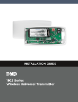
INSTALLATION GUIDE
1103 Series Universal Transmitter
Description
The 1103 Series Universal Transmitter is a two-input
transmitter with wall and case tamper typically used for
commercial re or burglary door and window applications.
The 1103 provides two internal magnetic reed switches and
an on-board terminal block to allow for external contact
wiring with an end-of-line resistor. Both sets of contacts,
internal and external, can be programmed to operate at the
same time allowing for two independent zones from one
transmitter. The 1103 features Disarm/Disable operation to
save battery life. Using the on-board LED the 1103 Series
Universal Transmitter provides built-in survey capability
to allow for single-person installations, eliminating the
requirement for an external survey kit. For added security, an internal case tamper switch and a wall
tamper switch are provided. The 1103E features 128-bit AES encryption.
Compatibility
All DMP XT Series and XR Series and all 1100 Series Wireless Receivers.
To enable encryption on 1135E models, Version 183 is required for XT and XR Series panels and Version 300 is
required for Wireless Receivers.
Included Components
• One 1103 Transmitter PCB mounted in a two-part housing (base and cover)
• One 3V lithium CR123A battery
• One magnet
• One Model 312 470K EOL Resistor
• Hardware pack
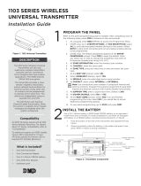
Programming the Transmitter in the Panel
Refer to the panel programming guide. If installing an 1103E, navigate to System Options. Select ALL or BOTH
to enable the use of wireless encryption. When prompted, enter an 8-digit passphrase. When installing an 1103,
navigate to Output Information. Enter an output number, output name, eight-digit serial number, supervision time,
and set the Trip with Panel Bell option to YES. Outputs operate with a 3 second response time when used with the
1103.
Note: When a receiver is installed, powered up, or the panel is reset, the supervision time for transmitters is reset.
If the receiver has been powered down for more than one hour, wireless transmitters may take up to an additional
hour to send a supervision message unless tripped, tampered, or powered up. This operation extends battery life for
transmitters. A missing message may display on the keypad until the transmitter sends a supervision message.
Using XT30/XT50 or XTL Series Panels
The 1103 has been designed primarily for use with the XR150/XR550 Series control panels. However, it can be used
with the XT30/XT50 or XTL Series panels as well. When used with those panels, the tamper indication is sent via
the internal contact zone only. If using the external contact, the internal contact must also be programmed in a
separate zone to provide tamper indication. In addition, the supplied magnet must be mounted next to the 1103
internal contact to restore the zone and allow the tamper switch to have priority. This issue does not exist when the
1103 is installed with the XR150/XR550 Series panels.
Selecting the Proper Location (LED Survey Operation)
The 1103 Transmitter provides a survey capability to allow one person to conrm transmitter communication
with the receiver while the cover is removed. The 1103 Transmitter PCB Red Survey LED turns on whenever data
is sent to the receiver then immediately turns off when the receiver acknowledgement is received. Pressing the
tamper switch is a convenient way to send data to the receiver to conrm operation. When the tamper switch is
pressed or released, the LED blinks once to indicate proper operation. When the transmitter does not receive an
acknowledgement from the receiver the LED remains on for about 8 seconds to let you know communication is
not established. Communication is also faulty when the LED ashes multiple times in quick succession. Relocate
the transmitter or receiver until the LED immediately turns off indicating the transmitter and receiver are
communicating properly. Proper communication between the transmitter and receiver is veried when for each press
Figure 1: Transmitter and Magnet

Digital Monitoring Products 1103 Installation Guide
2
or release of the tamper switch, the LED blinks immediately on and immediately off. Repeat this test to conrm ve
separate consecutive LED blinks. Any indication otherwise means proper communication has not been established.
Install the Transmitter
It is recommended the transmitter be mounted on the frame and the magnet be mounted on the door or window.
Mount the Transmitter
1. Remove the transmitter cover by pushing the button on the end of the cover and gently pulling upwards.
2. Remove the battery (if installed).
3. Remove the PCB by squeezing the PCB latch outward.
4. Hold the transmitter base in place with a magnet alignment marker near where you plan to mount the
magnet. See Figure 4 for magnet alignment marker locations.
5. Place one screw into the mounting hole location shown in Figure 2 and secure the housing to the surface.
6. Insert the included tamper screw and tamper as shown in Figure 2.
7. Reinsert the PCB into the transmitter base.
8. Install the battery in the battery location shown in Figure 4.
9. Snap the transmitter housing cover back on the base.
Mount the Magnet
Only one magnet is required for internal reed switch operation, either
located on the side or end of the enclosure. For internal contact operation,
the transmitter and magnet should have no more than 1” space between the
housings after installation. When mounting on metal (ferrous) surfaces, this
distance is slightly less.
Note: Locate the magnet at least 1/8” from the transmitter housing base.
The 1/8” distance ensures the magnet and transmitter housing have enough
space between them when mounted.
1. Place the magnet on the surface near one of the internal reed switch
Mounting
Screw
Figure 3: Magnet Assembly
Figure 4: Internal and External Contact Points
Red Survey
LED
External Contact
Terminal Block
Internal Contact
Magnetic Reed Switches
Battery Location
Mounting Hole
Magnet Alignment
Marker
Magnet Alignment
Marker
PCB Latch
Tamper
Tamper
Screw
Figure 2: Mounting the Transmitter

1103 Installation Guide Digital Monitoring Products
3
locations (see the magnet alignment markers
on the transmitter base).
2. Use the provided screws to secure the magnet
in place. See Figure 3.
Wiring and Connecting Contacts
When connecting an external contact to the terminal
block, DMP recommends using 18 or 22-gauge
unshielded wire. Do not use twisted pair or shielded
wire. It is recommended to locate a contact within
100 feet of the 1103 Universal Transmitter. Connect
the contact as normally open (N/O) or normally
closed (N/C) with the 470K end-of-line resistor. For
example: when programming the contact, select
normally open (N/O) if the contact is connected
as normally opened. Refer to the Contact option
under Zone Information in the appropriate panel
programming guide. See Figure 5. When using both
contacts, you must use consecutive zone numbers. Refer to the following examples:
• XR550 systems - zones
562 and 563 or zones 893 and 894
• XR150 systems - zones 523 and 524 or zones 593 and 594
• XT30/XT50 Series - zones 31 and 32 or zones 34 and 41
• XTLplus Series - zones 3 and 4
Note: For UL listed installations, program the external contact as Normally Closed (N/C). Refer to the Contact
option under Zone Information in the appropriate panel programming guide.
Installing or Replacing the Battery
Observe polarity when installing the battery. Use only 3.0V lithium batteries, DMP Model CR123A, or the equivalent
battery from a local retail outlet. For UL installations, only use #123 batteries manufactured by Energizer or CR123A
batteries manufactured by Panasonic or Tekcell.
Note: When setting up a wireless system, it is recommended to program zones and connect the receiver before
installing batteries in the transmitters.
1. If installed, remove the transmitter housing cover.
2. If replacing the battery, remove the old battery and dispose of it properly.
3. Place the 3.0V lithium battery in the holder as shown in Figure 4 and press into place.
4. Line the transmitter cover so the DMP logo is over the battery and snap the cover back into place.
Caution: Properly dispose of used batteries. Do not recharge, disassemble, heat above 212°F (100°C), or
incinerate. Risk of re, explosion, and burns.
Battery Life Expectancy
Typical battery life expectancy for DMP Model 1103 wireless transmitters is 5 years. DMP wireless equipment uses
two-way communication to extend battery life.
The following situations can reduce battery life expectancy:
• If a receiver is unplugged, or not installed.
Note: Transmitters continue to send supervision messages until a receiver returns an acknowledgement.
After an hour the transmitter only attempts a supervision message every 60 minutes.
• Programming the Disarm/Disable feature as NO in areas where frequent transmissions occur.
• Frequent transmissions, such as a door contact where messages are sent every time the door opens or closes.
• When installed in extreme hot or cold environments.
The following situation can extend battery life expectancy:
• Extend transmitter supervision time in panel programming.
• Programming the Disarm/Disable feature as YES in areas where frequent transmissions occur.
Note: If the Disarm/Disable operation is enabled, then the 1103 Universal Transmitter will not send trafc
reports or sensor activity notications to the panel. Additionally, the Zone Monitor feature (Chime) will be
disabled for the transmitter.
• Infrequent transmission trips, such as a window that rarely sends messages.
Figure 5: Contact Wiring
External Contact
1103
Transmitter
Window - External Contact
Door - Internal Contact
Series for N/C
Parallel for N/O
470k

LT-0702 1.05 © 2019 Digital Monitoring Products, Inc.
19064
800-641-4282
INTRUSION • FIRE • ACCESS • NETWORKS
www.dmp.com 2500 North Partnership Boulevard
Designed, Engineered and
Assembled in U.S.A.
Springeld, Missouri 65803-8877
FCC Information
This device complies with Part 15 of the FCC Rules. Operation is subject to the following two conditions:
1. This device may not cause harmful interference, and
2. this device must accept any interference received, including interference that may cause undesired operation.
The antenna used for this transmitter must be installed to provide a separation distance of at least 20 cm from all persons. It must not be co-
located or operated in conjunction with any other antenna or transmitter.
Changes or modications made by the user and not expressly approved by the party responsible for compliance could void the user’s authority to
operate the equipment.
Note: This equipment has been tested and found to comply with the limits for a Class B digital device, pursuant to part 15 of the FCC Rules.
These limits are designed to provide reasonable protection against harmful interference in a residential installation. This equipment
generates, uses and can radiate radio frequency energy and, if not installed and used in accordance with the instructions, may
cause harmful interference to radio communications. However, there is no guarantee that interference will not occur in a particular
installation. If this equipment does cause harmful interference to radio or television reception, which can be determined by turning the
equipment off and on, the user is encouraged to try to correct the interference by one or more of the following measures:
• Reorient or relocate the receiving antenna.
• Increase the separation between the equipment and receiver.
• Connect the equipment into an outlet on a circuit different from that to which the receiver is connected.
• Consult the dealer or an experienced radio/TV technician for help.
Commercial Fire
After all transmitters are in position, the WLS option of the panel’s Walk Test must be operated and all transmitters programmed for Fire (FI) or
Supervisory (SV) must show that their checkin message was received. Refer to the panel programming guide for Trip Counter for DMP Wireless
check-in Test (WLS) which describes that both numbers of the counter must match. If not and a failed wireless zone is displayed at END, decrease
that transmitters range with the receiver and perform the WLS Walk Test again.
For Fire Protective listed systems, the internal contact (magnet) cannot be used. For use only with normally open initiating devices that indicate
normal and off-normal (alarm) signals only (i.e. pull stations, heat detectors).
The 1103 must be installed within 3’ of the initiating device when not visible after installation, such as above a ceiling or within a wall. When
the 1103 is visible after installation and is seven feet or lower from the oor, it must be installed next to the initiating device. All wiring must be
inside the wall.
Industry Canada Information
This device complies with Industry Canada Licence-exempt RSS standard(s). Operation is subject to the following two conditions: (1) this device
may not cause interference, and (2) this device must accept any interference, including interference that may cause undesired operation of the
device.
Le présent appareil est conforme aux CNR d’Industrie Canada applicables aux appareils radio exempts de licence. L’exploitation est autorisée
aux deux conditions suivantes : (1) l’appareil ne doit pas produire de brouillage, et (2) l’utilisateur de l’appareil doit accepter tout brouillage
radioélectrique subi, même si le brouillage est susceptible d’en compromettre le fonctionnement.
Specications
Battery
Life Expectancy 5 years (normal operation)
Type 3.0V lithium CR123A
See Battery Life Expectancy for full details.
Frequency Range: 903-927 MHz
Dimensions
Transmitter Case 3.3” L x 1.6” W x 1.0” H
Color White
Housing Material Flame retardant ABS
Compatibility
1100X Wireless Receiver version 104 or higher
1100XH Wireless Receiver version 105 or higher
1100D Wireless Receiver version 104 or higher
1100DI Wireless Receiver Version 105 or higher
1100DH Wireless Receiver Version 105 or higher
XT50 Series panels with integrated wireless receiver
version 101 or higher
XTL Series panels with integrated wireless receiver
version 104 or higher
Patents
U. S. Patent No. 7,239,236
Ordering Information
1103-W Standard Universal Transmitter
1103E-W Encrypted Universal Transmitter
Certications
California State Fire Marshal (CSFM)
FCC Part 15 Registration ID CCKPC0191
New York City (FDNY COA #6167)
Industry Canada Registration ID 5251A-PC0191
ANSI/UL 365 Police Station Connected Burglar
ANSI/UL 609 Local Burglar Alarm Units and Systems
ANSI/UL 634 Connections and Switches for use with
Burglar Alarm Systems
ANSI/UL 1023 Household Burglar Alarm System Units
ANSI/UL 1076 Proprietary Burglar Alarm Units
ANSI/UL 1610 Central Station Burglar Alarm Units
ANSI/UL 864 Fire Protective Signaling Systems
/