Page is loading ...

Box1 Box2
Box3Box3
Box4
Parts Included
Hardware Kit 4225351-01
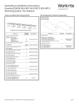
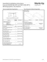
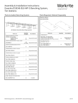
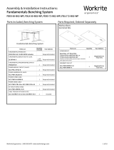
Assembly & Installation Instructions:
Sierra HXL Front Crank Workcenter SCFHXL36–48
& SCFHXL54–72
Required & Sold Separately
Styled or Flat Foot Kit
Worksurface
P 4 mm Allen Wrench
Qty: 1
M
M6×12 mm Flat Head
Machine Screw
Qty: 14
K Deep Hex Sha
Qty: 1
L Shallow Hex Sha
Qty: 1
B Top Leg
Bracket
Qty: 1
B Top Leg
Bracket
Qty: 1
O #12×¾" Phillips Head
Screw
Qty: 35
N
M6×14 mm Flat Head
Machine Screw
Qty: 18
C Short Bracket
Qty: 2
E Right End Bracket
Qty: 1
D Le End Bracket
Qty: 1
J Crank Handle Assembly
Qty: 1
I Crank Tube
Qty: 1
G Connector Bracket
Qty: 1F Rear Bracket
Qty: 2 F Rear Bracket
Qty: 1
A Leg
Qty: 1 A Leg
Qty: 1
or
For SCFHXL54-72 workcentersFor SCFHXL36-48 workcenters
H M6 × 12 mm
Flat Head
Cap Screw
Qty: 8
Verify that you have all the hardware and tools needed for the assembly
Check your cartons against the list above to verify that you have all the parts needed.
You will also need the following tools:
#2 tip Phillips screwdriver or drill/driver
#3 tip Phillips screwdriver or drill/driver
0.4126"
#3 Drive
0.134"3/4"
0.216"
#12 Screw Size
✓
or
If you do not have a Workrite tabletop
you will also need:
⅛" drill bit

Layout Legs and Brackets
Lay out Legs (A) and Brackets (B, C, D, E, F and G)
and Crank Tube (H) on the floor.
Attach Top Leg Bracket to Legs
Note: Right and Le Legs (A) and Top Leg Brackets (B) are
interchangeable.
Attach one Top Leg Bracket (B) to the top of each Leg (A)
using M6×14 mm Flat Head Screws (N).
Attach Short and Medium Brackets to Leg Assembly
Attach both Short Brackets (C)
to the Top Leg Brackets (B)using
M6×12mm Flat Head Screws (M).
Tighten securely.
Attach Le & Right Brackets (D & E)
to the Top Leg Brackets (B) using
M6×12mm Flat Head Screws (M).
Tighten securely.
or
2 of 8 Workrite Ergonomics | 800.959.9675 www.workriteergo.com
A A
E
E
A
A
A
A
D
D
M
M
M
M
B
B
B
C
C
C
C
P
F
F
F
G
H
1
2
To avoid stripping the threads, always
insert and make the first few turns
of the screw BY HAND with an Allen
wrench (P), ensuring it is in straight.
3
a
b
BB
B
NN
Two Rear Brackets (F) and one Connector
Bracket (G) for Workcenters 52" and wider .
One Rear Bracket (F) for
Workcenters up to 48".

Assemble Rear Brackets to Connector Bracket for Worksurfaces larger than 48"
For SCFHXL36, SCFHXL42 & SCFHXL48 workcenters: If your Worksurface is under 52"
wide you will not need to make an assembled Rear Bracket. You will use the single Rear
Bracket included with your frameset and proceed to Step 5.
For SCFHXL54, SCFHXL58, SCFHXL64 & SCFHXL72 Assemble
Rear Brackets (F) to Connector Bracket (G) using #M6×12 mm Flat
Head Cap Screws (H) included with Brackets.
Use this guide to determine the correct holes for mounting
based on the width of your workcenter.
Tighten securely.
Workrite Ergonomics | 800.959.9675 www.workriteergo.com 3 of 8
61"
55"
49"
43"
H
F
F
F
G
4
To avoid stripping the threads, always
insert and make the first few turns
of the screw BY HAND with an Allen
wrench (P), ensuring it is in straight.
52" Workcenters
58" Workcenters
64" Workcenters
70" Workcenters
Single Rear Bracket

Attach Rear Bracket to Right Leg
Attach Rear Bracket to back of Right Leg Cap using M6×12 mm
Flat Head Screws (H or M).
Tighten securely.
Note: M6×12mm Flat Head Screws are
provided with both the main hardware
kit (M) and with the connected brackets
(H). If your configuration uses an
Assembled Rear Bracket, use the Screws
(H) supplied with the brackets.
Attach Rear Bracket to Le Leg
Attach single Rear Bracket or Rear Bracket
assembly to back of Le Leg Bottom Bracket using
M6×12mm Flat Head Screws (H) or (M).
Tighten securely.
Note: M6×12mm Flat Head Screws are
provided with both the main hardware
kit (M) and with the connected brackets
(H). If your configuration uses an
Assembled Rear Bracket, use the Screws
(H) supplied with the brackets.
Attach Legs to Hex Shas and Crank Tube
Right Leg: Insert short end of Deep Hex Sha (K) into leg. Slide Crank Tube (I) over Deep Hex Sha. The Deep Hex
Sha is designed to go through the leg and engage the gear on the far side of the leg.
Le Leg: Pull Leg assemblies together and insert the short end of Shallow Hex Sha (L) into leg. Slide Crank Tube
(I) over Shallow Hex Sha. The Shallow Hex Sha is designed to go engage the gear on the near side of the leg.
4 of 8 Workrite Ergonomics | 800.959.9675 www.workriteergo.com
7
Right Leg
Back
5
Right Leg
Le Leg
I
H
H
M
M
I
K
L
6
a
b
b
a
Le Leg Back
Assembled
Rear Bracket
Assembled
Rear Bracket
Single Rear
Bracket
Single Rear
Bracket
Deep Hex Sha
Short end
Shallow Hex
Sha Short end
or
or
Crank hole
towards front
Crank hole
towards front

Attach Base to Worksurface — Workrite Worksurfaces
Note: If you do not have a Pre-Drilled Workrite
Worksurface, skip to Step 9.
Position leg assembly to align mounting holes in
brackets to pre-drilled holes in worksurface.
Attach at the four corner locations using #12×¾"
Phillips Head Screws (O). If you use an electric
screwdriver, be sure it is on the lowest torque
setting to avoid stripping the holes in the top.
With frame set positioned and the four corner
screws secure, attach frame set using the
remaining #12×¾" Phillips Head Screws (O).
Tighten securely.
Skip to Step 10.
Workrite Ergonomics | 800.959.9675 www.workriteergo.com 5 of 8
O
Workrite Pre-Drilled
Worksurface
8
b
b
c
c
a
Shown with Assembled
Rear Bracket
O

Attach Base to Worksurface — Non-Workrite Worksurfaces
Center the base assembly le to right.
Position the front to the worksurface to the tip
of the End Brackets (D and E) to the following
specification:
10½" for a 30" deep top
6¼" for a 24" deep top
Drill "×¾" deep pilot holes through all of the
brackets. You may wish to mark your drill bit so
you do not drill any more than ¾" deep and
damage tour worksurface top.
Take care to not drill through top!
Attach at the four corner locations using #12 × ¾"
Phillips Head Screws (O). If you use an electric
screwdriver, be sure it is on the lowest torque
setting to avoid stripping the holes in the top.
With frame set positioned and the four corner
screws secure, attach the frame set using the
remaining #12 × ¾" Phillips Head Screws (O).
Tighten securely.
6 of 8 Workrite Ergonomics | 800.959.9675 www.workriteergo.com
>¾"
10½" for 30"
6¼" for 24"
b
b
c
c
a
a
d
d
e
e
9
Mark drill bit
Back
Front
Tip of End
Bracket
Shown with Assembled
Rear Bracket
O
O

Attach Front Crank Drive & Handle Mount
The front crank drive and handle can be installed on
the right or le side as required. The steps shown
illustrate a right side handle installation (change to
opposite side for le installation).
Place the Crank Handle Assembly (J) into the Right
Leg as shown.
Attach with M6×14 mm Flat Head Machine Screw (N)
and tighten firmly.
Attach the Handle Mount
For Workrite Pre-Drilled Worksurfaces:
Locate the four pre-drilled holes for the handle
mount near the front of the worksurface. Install four
#12×¾" Phillips Head Screws (O) and tighten firmly.
Go to Step 13.
For Non-Workrite Worksurfaces:
Measure 3½" back from the front of top to the front
of the handle mount. Be sure the handle is not at an
angle. Drill ⅛"×¾" deep pilot holes. Take care not
to drill through top! Install four #12×¾" Pan Head
Wood Screws (O) and tighten firmly.
Workrite Ergonomics | 800.959.9675 www.workriteergo.com 7 of 8
Attach Feet (sold separately)
Refer to foot kit instructions for steps to
install your feet.
11
12
a
b
b
a
a
10
J
Shown without crank for clarity
N
3.5"
O
Front

Confirm All Screws are Tightened and Flip Table Over
Tighten all screws in frame assembly and tighten all screws connecting frame to worksurface. Flip table over
and adjust Leveling Glides if required so that table is steady and does not rock.
Position Crank
Pull out and turn handle to raise or lower table. Push the crank
under the desktop for storage.
Note: Force required to turn the front crank handle may be
slightly higher for the first few sit-to-stand cycles. This is normal
operation and the force necessary will decrease aer initial use.
Cleaning Instructions
To clean the Essentia legs, apply cleaner to a so cloth.
Suggested cleaners: Windex or Formula 409.
Do not use solvents and do not saturate or spray cleaners directly onto workcenter base.
✓
Parts & Accessories
Visit http://workriteergo.com/documentation/other/workrite_ergonomics_pricing_specification_guide.pdf for
replacement parts.
✓
Adjust Leveling Guides
If necessary, adjust leveling guides on table feet to level the worksurface.
#1500191 - Rev C
13
14
15
/