Page is loading ...

INSTALLATION SHEET
Secure-Com™ Cellular
Description
Secure-Com™ cellular allows you to connect a full-function cellular phone system as either the primary or backup
communication for DMP XR200, XR200-485, and XR2400F Command Processor™ Panels. The cellular unit connects to the
panel's battery terminals and the backup connector of the 893 Dual Phone Line Module.
What's Included
Secure-Com™ consists of the following:
• Secure-Com 3-watt Cellular Transceiver
• Secure-Com Cellular Interface Module
• Power cable for the transceiver
• All necessary phone cables
• Cellular antenna and antenna cable
A cellular handset (DMP Model 381) is available as an
option for your Secure-Com.
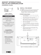
Installing the Hardware
Using the supplied Velcro tape, secure the Cellular
Interface Module to the Secure-Com Cellular Transceiver
as shown in Figure 1. Be sure to leave the LED on the
Cellular Interface Module visible to verify the unit is
operating properly.
Place the Cellular Transceiver and Interface Module in
the panel enclosure.
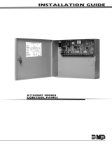
Wiring the Secure-Com Cellular System
1. Plug the Transceiver/Data cable from the Cellular
Interface Module into the Cellular Transceiver.
2. Connect the 356 Phone Cable between the 4-wire RJ11
jack on the Cellular Interface Module and the BACKUP
connector on the 893 Dual Phone Line Module.
3. Connect the antenna cable to the mini-UHF connector
on the Cellular Transceiver.
4. Install both units into the panel enclosure.
See Figure 1.
5. Connect the black wire on the power cable to the
battery negative terminal on the panel.
6. Connect the red wire on the power cable to the
battery positive terminal on the panel.
7. Plug the power cable connector into the Cellular
Transceiver.
The Secure-Com system draws 200mA standby current
and 2 Amps of current while transmitting.
Red Power LED
After applying power to the Secure-Com, the red power
LED on the Cellular Interface Module lights steady and
then flashes for five seconds. The LED then goes back to
steady to indicate the equipment is sensing the cellular
network through the antenna and there is sufficient
power from the panel's battery.
Figure 2: Secure-Com™ Cellular Wiring
Coax Cable
34
Red
Black
Power Cable
Phone line
to Telco
XR200, XR2400F, or XR200-485
Command Processor™ Panel
356 Cable
Secure-
Com
Cellular
Interface
Transceiver
Data Cable
Secure-
Com
Cellular
Transceiver
DMP Model 385
Cellular Antenna
Mini UHF
Connector
893 Dual
Phone Line
Module
Figure 1: Secure-Com™ Installation
Coax Cable
Power Cable
Secure-Com
Cellular
Transceiver
893
Module
Secure-
Com
Cellular
Interface
Battery

INTRUSION • FIRE • ACCESS • NETWORKS
2500 North Partnership Boulevard
800-641-4282
www.dmp.com
Made in the USA Springfield, Missouri 65803-8877
LT-0243 (12/02) © 2002 Digital Monitoring Products, Inc.
Turning Off the Cellular Phone
To turn off power to the cellular phone equipment, press the red LED button on the Cellular Interface Module. Pressing
it again restores power.
Activating Cellular Service
To activate the cellular service with a cellular provider, you will need to supply the Electronic Serial Number from the
Cellular Transceiver. See Figure 3. The provider will assign you a cellular ID number and an area code and phone number
for the cellular system. This information must be programmed into the Cellular Transceiver.
Follow the instructions in the NAM Programming Guide supplied with the cellular equipment to program the transceiver.
To program a Cellular Transceiver you will need the DMP Model 381 Handset. If you do not have a handset you may take
the Cellular Transceiver to a Motorola cellular dealer or service center, or you may contact DMP to purchase a
pre-programmed Cellular Transceiver.
About Cell-Miser™ Operation
XR200, XR200-485, and XR2400F panels support the cellular call restriction feature known as Cell-Miser™. This
programming option limits those calls made over a backup cellular phone line to zone alarms, Ambush, Phone Line 1
trouble, Abort, Recall Tests, and delayed events.
To use the XR200, XR200-485, or XR2400F panel with Cell-Miser, program the panel's second line for CELL. If you do not
want to use the Cell-Miser option, program the panel's second line for DD (digital dialer). All event information will be
sent over the cellular phone when the Line 1 analog line is inoperable.
Programming the Panel
Once the cellular equipment is installed and programmed, you must program the DMP panel to configure it for cellular
operation. Refer to the XR200/XR2400F Programming Guide (LT-0196) or the XR200-485 Programming Guide (LT-0466)
for more information.
Figure 3: Label on Cellular Transceiver
Electronic Serial Number
on Cellular Transceiver
MOTOROLA INC.
FCC ID: IHDT5ZX1 EE3
CANADA: 109 182 333A; TYPE: ZXKA
SUN3201AB H9 380C01PL01
DF9R682AASY B28
Specifications
Operating Voltage 12 VDC
Operating Current 200mA standby,
2 Amps transmitting
Compatibility
Secure-Com™ Cellular is compatible with XR200, XR2400F, and
XR200-485 Command Processor™ Panels.
The 893 or 893A Dual Phone Line Module is required to use
Secure-Com™ Cellular.
/