Page is loading ...

Ether-ComTM Single Port Router
Description
The Ether-ComTM Single Port Router installs on an SCS-1 Receiver and receives network communication from DMP
XR200, XR200-485, or XR2400F Command ProcessorTM panels. The router serves as an interface between the panel
and a computer network.
What’s Included
•Ether-Com Single Port Router
•Power adapter
•DMP Model 391 cable (RJ-45 cable with DB25 serial adapter)
What’s needed
Equipment needed to install the Ether-ComTM
• SCS-1 Receiver with available SCS-101 Network Interface Card
• Ethernet network connection (to receive incoming signals)
Additional equipment needed to program the Ether-ComTM
• Computer with available COM port
• HyperterminalTM communication (terminal emulation) software
• DMP Model 396 programming cable
Preparing for Setup
Before you configure the Ether-Com, you should get everything you need in place. Make sure you have the following
network information available. You can obtain this information from the system administrator for the network where
you are setting up the Ether-Com.
•IP address to assign to the Ether-Com
•Gateway address
•Subnet mask
Serial Connection to the Ether-ComTM
You must establish a serial connection to the Ether-Com with a computer in order to program it.
1. Connect the DMP Model 396 programming cable to the Ether-Com and to an available COM port on the back of
your computer. Do not connect the Ether-Com to the network at this point.
2. Click Start > Programs > Accessories > Communications > Hyperterminal, then double-click on Hypertrm.exe.
3. Enter a name for your connection, such as Ether-Com, then click OK.
4. From the “Connect Using” drop-down menu select “Direct to COM 1” or whichever COM port you are using on
your computer to connect to the Ether-Com, then click the Configure button.
5. In the COM properties window, select the following settings:
Bits per second: 9600
Data Bits: 8
Parity: None
Stop bits: 1
Flow Control: None
6. Connect the power cable to the Ether-Com and plug it in.
7. Click OK.
PROGRAMMING GUIDE

Ether-ComTM Installation Guide Digital Monitoring Products
2
Telnet Connection to the Ether-Com
As an alternative to a serial connection using the Model 396 programming cable to program the Ether-Com, you may
also connect it to the network and make a telnet connection across the network to program the Ether-Com. In order
to be able to make a telnet connection you must know the IP address currently programmed into the Ether-Com.
1. Use the supplied Model 391 cable to connect the serial port on the Ether-Com to the SCS-101 Network Interface
Card in the receiver.
2. Connect the Ethernet port on the Ether-Com to the computer network.
3. Plug in and connect the power cable.
4. From a computer attached to the same network as the Ether-Com, click Start > Run, type Telnet and click OK.
5. In the Telnet window click Connect > Remote System to open the Connect dialogue box.
6. In the Host Name field type the IP address of the Ether-Com.
7. In the “Port” field select “Telnet.”
8. In the TermType field select VT100, then click Connect.
Programming the Ether-Com
After configuring Hyperterminal and plugging in the Ether-Com’s power cord, Hyperterminal is prepared to connect to
the Ether-Com router. The following message should display at this point.
Ethernet Address: 00-80-a3-0f-4a-d4 Internet Address: 10.17.39.1
Flash Rom Version 2.0 (May 12, 1998)
Flash Version: 3.5/1 (970707)
Current Diagnostics report:
NVR Config:Normal Ram Size: 256 KB
CPU Speed: 10 MHz Gate Array: Rev 2
Flash Version: 3.5/1 (970707) Ethernet: None
Errors: Network
No network was detected. Press a key within
10 seconds to access bootmode commands>
Press the Return key to access the Boot> prompt.
Enter the following command at the Boot> prompt:
1. CHANGE BOOTP DISABLED
At the next Boot> prompt enter:
2. CHANGE DHCP DISABLED
At the third Boot> prompt enter:
3. CHANGE RARP DISABLED
Connect the Ether-Com to an Ethernet network after entering the above commands. It should be connected to the
actual network at the location where the Ether-Com will be permanently installed to help ensure that the IP
address you are assigning to the Ether-Com will not conflict with anything else on the network.

Digital Monitoring Products Ether-ComTM Installation Guide
3
4. INIT 451
The Ether-Com initialization will begin 5 seconds after pressing the Return key. If the Ether-Com has been properly
attached to a network and no other self-diagnostic errors are encountered, the Ether-Com will restart. The
following messages should then display:
DMP, Inc. ETHER-COM Initialization.....
Ethernet Address: 00-80-a3-0f-4a-d4 Internet Address: (Undefined)
Flash Rom Version 2.0 (May 12, 1998)
Flash Version: 3.5/1 (970707)
Current Diagnostics report:
NVR Config: Normal Ram Size: 256 KB
CPU Speed: 10 MHz Gate Array: Rev 2
Flash Version: 3.5/1 (970707) Ethernet: UTP
Errors: None
Skipping DHCP.
Skipping BOOTP.
Skipping RARP.
Checking 2 sections from flash:
From address 0x20004 to 0x20018, 281414 Bytes) -> not copied.
From address 0x64b5e to 0x210000, 7712 Bytes) -> copied.
Load Complete - Boot in Progress
Press the Return key to display the username> prompt. Enter your name, followed by the Return key to display
the Local1> prompt.
Before any configuration changes can be made, you must become the privileged user. To do this, type SET PRIV
followed by the Return key. The display will then change to password>. Type SYSTEM, then press the Return key.
This changes the Ether-Com to the Local>> prompt.
Obtain the following information from your system administrator.
Enter the following commands at the Local>> prompts:
1. CHANGE IP ADDRESS xxx.xxx.xxx.xxx
.
Enter the IP address for the unit you received from the
system administrator. Note: This address must be unique to the network.
2. CHANGE GATEWAY xxx.xxx.xxx.xxx
.
Enter the IP address for the Gateway address you received
from the system administrator.
3. CHANGE SUBNET MASK xxx.xxx.xxx.xxx
.
Enter the subnet mask provided by the system
administrator.
4. CHANGE SPEED 9600. If you change the baud rate, you must change the baud rate in Hyperterminal
and then resume your programming session. To change the baud rate in Hyperterminal, select File >
Properties click the Configure button. Select the new baud rate from the “Bits Per Second” drop-
down menu and click OK twice. You may now resume your Ether-Com programming session.
5. CHANGE FLOW CONTROL NONE.

LT-0424 (6/02) © 2001 Digital Monitoring Products, Inc.
6. CHANGE DEDICATED TCP :2001U.
Note: If you are installing the Ether-Com at a panel, then enter
CHANGE DEDICATED TCP xxx.xxx.xxx.xxx:2001U where “xxx” is the IP address of the receiver
at the central station.
7. CHANGE AUTOSTART ENABLED
8. SHOW SERVER
- This command checks and confirms the unit’s IP address, Subnet Mask and the
Gateway address.
10. SHOW PORT
- This command checks and confirms that speed, flow control, dedicated service, and
autostart options are set correctly. (The unit is now ready to be connected to the SCS-101 line card.)
Important Note
Once the Ether-Com is configured, no local access is allowed through the serial port while the unit is connected to the
network. To reconfigure the Ether-Com programming you must remove power from the unit, disconnect it from the
network, and then reapply power. Press the Enter key within 10 seconds to enter the configuration mode. Enter the
command FLUSH NVR to return the unit to its factory defaults. This erases all options including the IP address.
11. LOGOUT
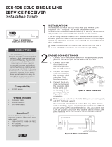
Figure 1: Ether-Com
Serial
PwrResetEthernet
TM
DB25 Port
8-pin RJ45 jack
Network connection active
Power OK
Network data activity
Serial data activity
6 VDC 700mA power
Use paper clip
to reset
a
INTRUSION • FIRE • ACCESS • NETWORKS
2500 North Partnership Boulevard
800-641-4282
www.dmp.com
Made in the USA Springfield, Missouri 65803-8877
/