Page is loading ...

INSTALLATION
8365
1. Mortise Cutouts
Hold lock against frame at desired level. Mark the lock's horizontal
centerline on the frame and transfer that mark to the door.
Determine the vertical centerline of the door thickness and
mark this on both the door and the frame.
Using these centerline references, cut out the frame lock
mortise and the door armature mortise, as illustrated.
2. Lock Mounting Tabs
Temporarily fasten the two mounting tabs under the lock
flanges. Insert the lock assembly into the frame cavity until the
tabs are resting on top. Mark the location of the tab mounting
holes.
Drill and countersink these four holes to accept the 3/16”
screws provided.
Remove tabs from lock. Mount the tabs inside the frame.
3. Wire and Mount Lock
Remove endcap.
Set voltage jumpers as follows:
12VDC operation = two jumpers are used.
Contact pins 1 to 2 and 3 to 4.
24VDC operation = only one jumper is used.
Contact pins 2 to 3. (factory setting)
Connect the positive (+) power lead to the red and the negative
(-) lead to the white wire.
Connecting wire should be of sufficient gauge for the lock
being installed and the distance being run.
See table for current draw
specifications and wiring
gauge chart.
Secure lock on tabs in
mortise cavity, carefully
applying thread locking
compound to the hardware
provided, as in Fig. 1
®
MicroMag
®
Mortise Electromagnetic Lock
©2011 RUTHERFORD CONTROLS INT’L CORP. WWW.RUTHERFORDCONTROLS.COM
USA: 2517 SQUADRON COURT, SUITE 104, VIRGINIA BEACH, VA 23453 • CANADA: 210 SHEARSON CRESCENT, CAMBRIDGE, ON N1T 1J6
PHONE • 1.800.265.6630 • 519.621.7651 • FAX: 1.800.482.9795 • 519.621.7939 • E-MAIL: SALES@RUTHERFORDCONTROLS.COM
IS8365
PCN110045
R07/11SH
Instructions
Pre-Installation Instructions
1. This product must be installed according to all applicable
building and life safety codes.
2. Due to the variety of mounting configurations available with
this product, a survey and assessment of the physical area
in which the product will be installed must be performed.
3. The door frame must be inspected and deemed structurally
sound prior to installation of the electromagnetic lock. The
structural integrity of the mounting surfaces must be strong
enough to meet or exceed the holding force of the product.
4. The product must be protected from potential damage due
to intruders or tampering.
5. The product should be installed in a location that will not
hinder or create a potential safety hazard to authorized
personnel accessing the protected area.
6. Because electromagnetic locks are used in a variety of
applications and different door frame configurations, an
experienced installer with knowledge of this product must
make a determination of the optimal mounting method
for this specific application.
7. Do not install this product on the exterior of buildings.
8. Do not use as a doorstop. This will void warranty.
9. Installation of this product should be done by an
experienced installer with knowledge of this product.
NOTE: It is highly recommended that thread locking compound
be applied to all screws during installation to reduce chance of
screws loosening over extended time.
WARNING: Improper installation, maintenance, inspection or
usage of the product or any related accessories or parts may cause
the electromagnetic lock, armature plate and associated hardware
to disengage and fall, causing serious bodily injury and property
damage. Rutherford Controls Int'l Corp. will not be liable to the
installer, purchaser, end user or anyone else for damage or injury
to person or property due to improper installation, care, storage,
handling, maintenance, inspection, abuse, misuse or act of God or
nature involving this product or any related accessories or parts.
PLEASE DELIVER ALL INSTALLATION INSTRUCTIONS TO
THE END-USER UPON COMPLETION OF THE INSTALLATION.

8365 Electromagnetic Lock Installation Instructions (Continued)
4. Mount Armature
Using centerline references on the door and illustration provided,
drill the four “U” clamp mounting holes.
Position the “U” clamp inside door as shown on Fig. 2. Insert the
two pan head sex nuts from the outside of the door and through
the “U” clamp. Insert the two button head hex bolts from the
inside of the door and secure into the sex nuts.
Position bolt with rubber head through armature plate. Add 3
washers (steel - rubber - steel) onto threads. Carefully apply
thread-locking compound to exposed thread and mount onto the
“U” clamp.
NOTE: Do not over tighten. The armature plate must be allowed to
pivot on the mounting bolt to allow proper alignment with the
magnet surface. If the plate is not aligned with the magnet surface,
the lock may lose holding force or not lock at all.
The head of the armature mounting bolt ships with a rubber
washer affixed to it. This washer should project slightly beyond
the surface of the armature plate. This is to allow the washer to
expand when power is removed and break the air vacuum
between the plate and the magnet surface. If this washer is
removed or trimmed, the lock will appear to have some holding
force even when power is removed.
5. Validate
With a release device already installed, energize circuit and close
door gently. If magnet does not secure, verify that armature plate
is making contact with face of magnetic block. If necessary,
install additional steel washers behind armature plate to move
armature plate closer to block face and retest.
Inspection and Maintenance
This product and all related accessories or parts must be inspected and
maintained on a quarterly basis. Contacting surfaces of the
electromagnetic lock and armature plate must be kept free of
contaminating materials. Surfaces must be cleaned periodically with a
non-abrasive cleaner.
All mounting fasteners must be inspected on a quarterly basis. When
properly installed, the ends of the armature plate allow a slight
movement but the plate will feel secure when grasped at the bolt. There
should be no movement to the mounting bracket or housing of the
electromagnetic lock.
For added safety, thread locking compound has been provided for the
armature plate bolt and the four electromagnetic lock mounting screws.
WARNING: Improper installation, maintenance, inspection or usage of
the product or any related accessories or parts may cause the
electromagnetic lock, armature plate and associated hardware to
disengage and fall, causing serious bodily injury and property damage.
PLEASE DELIVER ALL INSTALLATION INSTRUCTIONS TO THE
END-USER UPON COMPLETION OF THE INSTALLATION.
For product support, parts and ordering information contact:
Rutherford Controls Int’l Corp.
USA: 2517 Squadron Court, Suite 104
Virginia Beach, VA 23453
Canada: 210 Shearson Crescent
Cambridge, ON N1T 1J6
Phone: 1-800-265-6630 / 1-519-621-7651
Fax: 1-800-482-9795 / 1-519-621-7939
E-mail: [email protected]
Website: www.rutherfordcontrols.com
NOTE: All RCI electromagnetic locks must be powered with filtered and regulated DC power supplies such as the RCI 10 Series UL Listed power
supply. RCI offers a full line of power supplies and switching devices that are suitable for use with the 8300 Series locks.
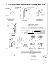
2

8365
Electromagnetic
Lock
Mounting
Tab
Frame
Extrusion
Frame
Sliding Door
A
B
Exterior
Exterior
Interior
Side
Interior
Side
Shock absorbing
rubber washer
Metal
washers
C
L
C
L
cut
out
cut
out
C
L
C
L
F
G
H
H
I
C
L
C
L
G
H
H
I
E
"U" Clamp
Do not over tighten
preventing movement.
Frame
Sliding Door
Inches
Fractions
Inches
Decimal
(mm)
metric
1-3/8
1.38 8.00 1.31 5.19 1.05 0.55 0.31
0.47
34.9 203.2 33.3 131.8 26.6 14.0 7.9
12.0
8 1-5/16 5-3/16 1-1/16
A B E F G H I (interior) I (exterior)
FRAME DOOR
9/16 5/16 1/2
Voltage Current
12VDC 0.40A
24VDC 0.20A
NOTE: Specifications are subject to change without notice.
8365 Electromagnetic Lock Installation Instructions (Continued)
3
Fig.1
Fig.2

Total One Way
Length of 1/4A 1/2A 3/4A 1A 1-1/4A 1-1/2A 2A 3A
Wire Run (ft.)
100 24 20 18 18 16 16 14 12
150 22 18 16 16 14 14 12 10
200 20 18 16 14 14 12 12 10
250 18 16 14 14 12 12 12 10
300 18 16 14 12 12 12 10 --
400 18 14 12 12 10 10 -- --
500 16 14 12 10 10 -- -- --
750 14 12 10 10 -- -- -- --
1000 14 10 10 -- -- -- -- --
1500 12 10 -- -- -- -- -- --
Total One Way
Length of 1/4A 1/2A 3/4A 1A 1-1/4A 1-1/2A 2A 3A
Wire Run (ft.)
100 20 18 16 14 14 12 12 10
150 18 16 14 12 12 12 10 --
200 16 14 12 12 10 10 -- --
250 16 14 12 10 10 10 -- --
300 16 12 12 10 10 -- -- --
400 14 12 10 -- -- -- -- --
500 14 10 10 -- -- -- -- --
750 12 10 -- -- -- -- -- --
1000 10 -- -- -- -- -- -- --
1500 10 -- -- -- -- -- -- --
Load Current @24V
Load Current @12V
Wire Gauge Chart courtesy of Electronic Locking Devices by John L. Schum
WIRE GAUGE SELECTIONS
8365 Electromagnetic Lock Installation Instructions (Continued)
©2011 RUTHERFORD CONTROLS INT’L CORP. WWW.RUTHERFORDCONTROLS.COM
USA: 2517 SQUADRON COURT, SUITE 104, VIRGINIA BEACH, VA 23453 • CANADA: 210 SHEARSON CRESCENT, CAMBRIDGE, ON N1T 1J6
PHONE • 1.800.265.6630 • 519.621.7651 • FAX: 1.800.482.9795 • 519.621.7939 • E-MAIL: SALES@RUTHERFORDCONTROLS.COM
4
/