Assa Abloy 1584 Series Installation guide
- Type
- Installation guide
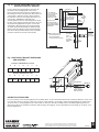
Assa Abloy 1584 Series is an electromagnetic lock designed for use on both single and double doors. It is a heavy-duty lock that is ideal for high-security applications. The lock is easy to install and can be mounted on either the door frame or the door itself. It features a tamper-resistant design and is made of durable materials. The lock is also available in a variety of finishes to match any décor.
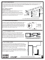
The Assa Abloy 1584 Series electromagnetic lock is a versatile lock that can be used in a variety of applications. It is ideal for use on exterior doors, interior doors, and even fire doors. The lock can be used to control access to sensitive areas, such as data centers, server rooms, and storage facilities. It can also be used to secure entrances to buildings, such as schools, hospitals, and offices.
Assa Abloy 1584 Series is an electromagnetic lock designed for use on both single and double doors. It is a heavy-duty lock that is ideal for high-security applications. The lock is easy to install and can be mounted on either the door frame or the door itself. It features a tamper-resistant design and is made of durable materials. The lock is also available in a variety of finishes to match any décor.
The Assa Abloy 1584 Series electromagnetic lock is a versatile lock that can be used in a variety of applications. It is ideal for use on exterior doors, interior doors, and even fire doors. The lock can be used to control access to sensitive areas, such as data centers, server rooms, and storage facilities. It can also be used to secure entrances to buildings, such as schools, hospitals, and offices.


-
 1
1
-
 2
2
-
 3
3
-
 4
4


Assa Abloy 1584 Series Installation guide
- Type
- Installation guide
Assa Abloy 1584 Series is an electromagnetic lock designed for use on both single and double doors. It is a heavy-duty lock that is ideal for high-security applications. The lock is easy to install and can be mounted on either the door frame or the door itself. It features a tamper-resistant design and is made of durable materials. The lock is also available in a variety of finishes to match any décor.
The Assa Abloy 1584 Series electromagnetic lock is a versatile lock that can be used in a variety of applications. It is ideal for use on exterior doors, interior doors, and even fire doors. The lock can be used to control access to sensitive areas, such as data centers, server rooms, and storage facilities. It can also be used to secure entrances to buildings, such as schools, hospitals, and offices.
Ask a question and I''ll find the answer in the document
Finding information in a document is now easier with AI
Related papers
-
Assa Abloy Sargent 700 Installation guide
-
-
-
-
-
Assa Abloy IN120 User manual
-
-
Assa Abloy Securitron M38L Installation guide
-
-
Other documents
-
Bazooka Power Rail Universal Roll Bar Owner's manual
-
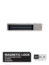 W Box Technologies 600 LB HOLDING FORCE Installation guide
-
 Visionis FPC-5640 One Door Access Control Outswinging Door 600lbs Maglock User guide
-
 Visionis FPC-5656 One Door Access Control Outswinging Door 1200lbs Maglock User guide
-
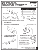 Sargent POWERGLIDE 281 Installation guide
-
 Sargent 1431 series Installation Instructions Manual
-
Soyal AR-0300M Electromagnetic Lock Installation guide
-
 Sargent 351EHT Operating instructions
-
none 80012 Installation guide
-
Gianni Industries PH-500 Series Installation guide


