Page is loading ...

©2011 RUTHERFORD CONTROLS INT’L CORP. WWW.RUTHERFORDCONTROLS.COM
USA: 2517 SQUADRON COURT, SUITE 104, VIRGINIA BEACH, VA 23453 • CANADA: 210 SHEARSON CRESCENT, CAMBRIDGE, ON N1T 1J6
PHONE • 1.800.265.6630 • 519.621.7651 • FAX: 1.800.482.9795 • 519.621.7939 • E-MAIL: SALES@RUTHERFORDCONTROLS.COM
Installation Instructions
1. For new installations, surface mount 0161 strike first, then install exit device accordingly maintaining a
minimum of
3
⁄16" clearance.
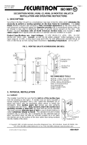
2. Determine the horizontal center line ‘G’ of the Pullman Latch of the exit device, and transfer to frame stop.
(see fig. 1)
3. Determine the vertical center line of the Electric Strike ‘X’ by adding
3
⁄4" to dimension "R" (See Fig.1)
and measure from the push side of the door to frame stop for ‘X’.
4. Prepare door jamb as per template drawing for full surface mounting. (see preparation "V")
5. Ensure that strike insert is placed in the center most position on the faceplate prior to installation.
This allows for maximum adjustability when installation is complete (see Fig. 2).
6. Connect wires from
power source to terminal screws on strike (polarity is not observed).
7. Using slotted holes in chassis, install exit device electric strike with 2 SHCS
1
⁄4 - 20 x 1”, socket head cap
screws provided.
8. Adjust chassis and electric insert (if necessary), horizontally, until Pullman Latch engages when door is
closed. Finally tighten screws.
Important: Be sure exit device dead locks when door is closed before proceeding to step 9.
9. Mark, drill and tap for the locking screws provided, and install to secure final location with
2 SHCS
1
⁄4 - 20 x 1”, screws provided.
Note:
If further adjustment is needed later, to correct door or weatherstrip misalignments, horizontally move
insert on its furrows by loosening screws under the face plate, and re-tighten when in the corrected
position (Fig. 2.).
Important:
The 0161 Electric Strike is never to be used as a door stop. Please install stops on frame in appropriate
locations. Ensure the exit device functions as intended for life safety concerns by verifying electric strike
and exit device compatibility. Maximum latch projection is essential to obtain full holding force.
I N S T A L L A T I O N
0 SERIES COMMERCIAL ELECTRIC STRIKE
CENTERLINE LATCH ENTRY FOR RIM EXIT DEVICE
0161
IS0161
PCN110045
R07/11SH

0161 Series Installation Instructions (Continued)
Template For 0 Series Strikes
MODEL # 0161
Preparation for mortising electric
insert for model 0161
Vertical center line of
0161
MEASUREMENT
FRACTIONAL
INCHES
DECIMAL INCHES
METRIC mm
X
G
V
M
M
O
P
C
Q
K
K
PREPARATION
Insert Semi-mortise Mounting
Preparation “V”
Future alignment problems can be
corrected by loosening the two
insert screws and moving the
insert horizontally across the
furrows. Original preparation is not
disturbed. (Fig.2).
IMPORTANT
If Exit Device Strike (supplied
with device) is of
1
⁄2" or
5
⁄8"
projection, please use" Insert
Semi-mortise Mounting" or
Preparation "V".
Exit
Device
Door
Edge
R
G
c
L
Note: DO NOT SCALE
SPECIFICATIONS SUBJECT TO
CHANGE WITHOUT NOTICE.
Fig.1
©2011 RUTHERFORD CONTROLS INT’L CORP. WWW.RUTHERFORDCONTROLS.COM
USA: 2517 SQUADRON COURT, SUITE 104, VIRGINIA BEACH, VA 23453 • CANADA: 210 SHEARSON CRESCENT, CAMBRIDGE, ON N1T 1J6
PHONE • 1.800.265.6630 • 519.621.7651 • FAX: 1.800.482.9795 • 519.621.7939 • E-MAIL: SALES@RUTHERFORDCONTROLS.COM
C 1
5
/8 1.625 41.3
G
K 4
1
/8 4.125 105
M
O
5
/16" .312 8
P 2
1
/
2
2.5 63
Q 1
3
/8 1.375 35
V
X
Horizontal center line of
Pullman Latch
1/4 - 20 Tap
/