Page is loading ...

Operating Instructions
surfaceCONTROL 3D 35xx
SC3500-80
SC3510-80
SC3500-120
SC3510-120

MICRO-EPSILON
MESSTECHNIK
GmbH & Co. KG
Koenigbacher Str. 15
94496 Ortenburg / Germany
Tel. +49 (0) 8542 / 168-0
Fax +49 (0) 8542 / 168-90
e-mail [email protected]
www.micro-epsilon.com

surfaceCONTROL 3D 35xx
Contents
1. Safety ........................................................................................................................................ 5
1.1 Symbols Used ................................................................................................................................................. 5
1.2 Warnings .......................................................................................................................................................... 5
1.3 Notes on CE Marking ...................................................................................................................................... 6
1.4 Intended Use ................................................................................................................................................... 6
1.5 Proper Environment ......................................................................................................................................... 6
2. Light Source ............................................................................................................................. 7
3. Functional Principle, Technical Data ....................................................................................... 8
3.1 Short Description ............................................................................................................................................. 8
3.1.1 Measuring Principle ........................................................................................................................ 8
3.1.2 System Setup ................................................................................................................................. 8
3.1.3 Special Performance Features ....................................................................................................... 8
3.2 Technical Data ................................................................................................................................................. 9
3.3 LED Displays .................................................................................................................................................. 10
4. Delivery ................................................................................................................................... 11
4.1 Unpacking, Included in Delivery.................................................................................................................... 11
4.2 Storage .......................................................................................................................................................... 11
5. Installation and Mounting ...................................................................................................... 12
5.1 Attachment and Mounting ............................................................................................................................. 12
5.2 Electrical Connections ................................................................................................................................... 16
5.2.1 General ......................................................................................................................................... 16
5.2.2 Supply Voltage (Power) ................................................................................................................ 16
5.2.3 Gigabit Ethernet Connection ........................................................................................................ 17
5.2.4 Multi-Function Connection I/O ..................................................................................................... 18
5.2.4.1 Digital Signals ........................................................................................................... 18
5.2.4.2 Electrical Parameters of Digital Inputs, Multi-Function Connection ......................... 19
5.2.4.3 Electrical Parameters of Digital Outputs, Multi-Function Connection ...................... 20
5.3 Installation Instructions .................................................................................................................................. 20
5.4 Commissioning .............................................................................................................................................. 20
6. Operation ................................................................................................................................ 21
6.1 Turning On ..................................................................................................................................................... 21
6.2 Operating Programs ...................................................................................................................................... 21
6.3 Installation ...................................................................................................................................................... 21
6.3.1 Requirements ............................................................................................................................... 21
6.3.2 Connecting surfaceCONTROL 3D 35xx to the PC ....................................................................... 21
6.4 Notes for Operation ....................................................................................................................................... 22
6.4.1 Measuring Range ......................................................................................................................... 22
6.4.2 Calibration .................................................................................................................................... 22
6.4.3 Positioning of Sensor and Test Object ......................................................................................... 23
6.4.3.1 General ...................................................................................................................... 23
6.4.3.2 Alignment with Crosshair .......................................................................................... 23
6.4.4 Exposure ....................................................................................................................................... 25
6.5 Temperature ................................................................................................................................................... 25
6.6 Error Influences.............................................................................................................................................. 26
6.6.1 Reflection Factor of the Surface of the Target .............................................................................. 26
6.6.2 Color Differences .......................................................................................................................... 26
6.6.3 Temperature Influences ................................................................................................................ 26
6.6.4 External Light ................................................................................................................................ 26
6.6.5 Mechanical Vibrations .................................................................................................................. 26
6.6.6 Surface Roughness and Texture .................................................................................................. 26
6.6.7 Shadowing Effects and Multiple Reflections ................................................................................ 27
6.7 Cleaning ......................................................................................................................................................... 27
7. Liability for Material Defects .................................................................................................. 28
8. Service, Repair ...................................................................................................................... 28
9. Decommissioning, Disposal .................................................................................................. 28
Appendix ................................................................................................................................. 29
A 1 Accessories ............................................................................................................................ 29
A 2 Optional Accessories ............................................................................................................. 29
A 3 Genicam surfaceCONTROL Parameters ............................................................................... 31

surfaceCONTROL 3D 35xx

Seite 5
Safety
surfaceCONTROL 3D 35xx
1. Safety
The handling of the sensor assumes knowledge of the operating instructions.
1.1 Symbols Used
The following symbols are used in this operating instructions:
Indicates a hazardous situation which, if not avoided, may result in minor or moderate injury.
Indicates a situation that may result in property damage if not avoided.
Indicates a user action.
i
Indicates a tip for users.
Measure
Indicates hardware or a software button/menu.
1.2 Warnings
Do not look directly into the light source of the sensor.
> Risk of injury, damage to the eyes and skin
Connect the power supply and the display/output device according to the safety regulations for
electrical equipment.
> Risk of injury
> Damage to or destruction of the sensor
Avoid shocks and impacts to the sensor.
> Damage to or destruction of the sensor
The supply voltage must not exceed the specified limits.
> Damage to or destruction of the sensor
Avoid constant exposure of the sensor to dust or splashes of water by appropriate methods such as
blowing or using a protective housing.
> Damage to or destruction of the sensor
Do not touch the protective windows of the optics. Wipe off any fingerprints immediately with pure
alcohol and a clean cotton cloth with no streaks.
> Failure of the measuring device
Protect the cables against damage.
> Failure of the measuring device
The sensor housing may only be opened by authorized persons.
> Damage to or destruction of the sensor
Do not plug or unplug devices during the operation.

Seite 6
Safety
surfaceCONTROL 3D 35xx
1.3 Notes on CE Marking
The following apply to the surfaceCONTROL 3D 35xx:
- EU Directive 2014/30/EU
- EU Directive 2011/65/EU
Products which carry the CE mark satisfy the requirements of the EU directives cited and the relevant applicable
harmonized European standards (EN). The measuring system is designed for use in industrial environments.
The EU Declaration of Conformity and the technical documentation are available to the responsible authorities according
to the EU Directives.
1.4 Intended Use
- The surfaceCONTROL 3D 35xx measuring system is designed for use in industrial applications.
Non-contact optical measurement of diffuse reflective surfaces
Quality monitoring as well as form/position and surface inspection
- The system must only be operated within the limits specified in the technical data, see Chap. 3.2.
- The sensor must be used in such a way that no persons are endangered or machines and other material goods are
damaged in the event of malfunction or total failure of the sensor.
- Take additional precautions for safety and damage prevention in case of safety-related applications.
1.5 Proper Environment
- Protection class
Sensor: IP67 (only applies in the case of connected output connectors and/or installed protective caps)
Optical paths during operation are excluded from the protection class.
Contamination of the paths causes impairment or failure of the function.
The IP67 protection class is a specification that is limited to protection from dust and water. Oil, steam and emulsion
effects are not included in this protection class and must be evaluated separately.
- Temperature range
Operation: 0 ... +45 °C
1
(+32 ... +113 °F) (with appropriate heat dissipation)
Storage: -20 ... +70 °C (-4 ... +158 °F)
- Humidity: 20 ... 80 % (non condensing)
- Ambient pressure: Atmospheric pressure
1) Max. permissible operating temperature depends on installation scenario, thermal connection and operating mode.
If necessary, external heat dissipation must be used to ensure that the sensor’s internal temperature of 60 °C is not ex-
ceeded.

Seite 7
Light Source
surfaceCONTROL 3D 35xx
2. Light Source
The surfaceCONTROL 3D 35xx sensor works with an LED lighting unit. Measurement is performed using blue light at the
dominant 459 nm wavelength. The sensor is included in risk group 2 according to EN 62471: 2008.
Do not look into the lens. Consciously close your eyes or immediately turn away if the optical radia-
tion enters the eye.
The warning sign below is attached to the sensor housing on the top and bottom:
Fig. 1 LED warning sign
i
If both warning labels are covered over when the unit is installed, the user must ensure that supplementary labels
are applied.

Seite 8
Functional Principle, Technical Data
surfaceCONTROL 3D 35xx
3. Functional Principle, Technical Data
3.1 Short Description
3.1.1 Measuring Principle
surfaceCONTROL 3D 35xx is a sensor for non-contact and non-destructive optical and three-dimensional detection of
components with diffuse reflective surfaces. It operates according to the optical triangulation principle (fringe projection):
- Using a matrix projector, a sequence of patterns is projected onto the surface of the test object.
- The light of the patterns diffusely reflected by the test object surface is recorded by two cameras.
- The three-dimensional surface of the test object is then calculated from the recorded image sequence and the ar-
rangement of the two cameras to each other.
3
2
1
1
Cameras
2
Projection unit
3
Fringe light
Fig. 2 Measuring Principle
3.1.2 System Setup
The surfaceCONTROL 3D 35xx measuring system is a compact sensor with an integrated controller. All necessary
integral parts are combined in one housing.
3.1.3 Special Performance Features
- surfaceCONTROL 3D 35xx is characterized by a compact design and highly accurate measurements while at the
same time achieving high throughput of 3D points.
- Data are output via Gigabit Ethernet. GigE Vision compatibility allows the sensor to be integrated in different ways:
Software provided by Micro-Epsilon
Software by third parties
SDK
- Gigabit Ethernet as a fast default connection to the PC
- The sensor additionally offers an I/O interface:
Querying sensor states
External control, e.g., triggering
System integrators User
SC3500
- supported by 3D-View
- supported by 3DInspect
- supported by SDK
- supports GigE Vision
- supported by DefMap3D (li-
censing via additional dongle)
SC3510
- unlocking of functional
extension 3DInspect
Automation
Customers require their own software Micro-Epsilon software

Seite 9
Functional Principle, Technical Data
surfaceCONTROL 3D 35xx
3.2 Technical Data
Model SC3500-80 SC3510-80 SC3500-120 SC3510-120
Measurement area
length x width
(at height)
x * y (z)
Start expanded area 55 mm x 42 mm at 110 mm 87.5 mm x 62.5 mm at 171 mm
Start 67.5 mm x 46 mm at 120 mm 107.5 mm x 70 mm at 191 mm
Mid 80 mm x 50 mm at 130 mm 120 mm x 75 mm at 206 mm
End 77.5 mm x 52 mm at 140 mm 123.5 mm x 80 mm at 221 mm
End expanded area 75 mm x 54 mm at 150 mm 122 mm x 82.5 mm at 241 mm
Working distance
z 130 ±10 mm 206 ±15 mm
expanded z 130 ±20 mm 206 ±35 mm
Resolution
x, y 40 µm 60 µm
z
1
1.0 µm 2.0 µm
Repeatability
z(s)
1
< 0.4 µm < 0.8 µm
Acquisition time
2 3
0.2 … 0.4 s
Light source LED
Power supply 18 … 30 VDC
Max current consumption 0.5 ... 2.5 A
Digital interface
Gigabit Ethernet (GigE Vision / GenICam) / PROFINET
4
/ EtherCAT
4
/
EtherNet/IP
4
Digital in-/outputs
4 digital I/Os for which parameters can be set (for external trigger, sensor
control, output of sensor states)
Connection
8-pin M12 socket for Gigabit Ethernet, 12-pin M12 socket for digital I/Os,
4-pin M12 plug for power supply
Mounting 3 mounting holes (installation can be reproduced with centering sleeves)
Temperature range
Storage -20 … 70 °C (-4 ... +158 °F)
Operation
5
0 … 45 °C (+32 ... +113 °F)
Shock (DIN-EN 60068-2-27) 15 g / 6 ms in XY-Achse, 1000 shocks each
Vibration (DIN-EN 60068-2-6) 2 g / 20 … 500 Hz in XY axis, 10 cycles each
Protection class (DIN-EN60529) IP67
Material
Aluminum housing, passive cooling;
external cooling optionally available (see accessories)
Weight 1.9 kg
Control and Display Elements 3 LEDs (for sensor state, power, data transmission)
Sensor-SDK Micro-Epsilon 3D Sensor-SDK
3D evaliation software Micro-Epsilon 3DInspect
Functional extension
- 3DInspect Automation - 3DInspect Automation
1) Measured on measuring object with cooperative surface in the mid of the measuring range while the “EnhancedSNR”
parameter is enabled and a 3x3 mean value filter is used once at a consistent room temperature of 20 ± 1 °C.
2) Duration that the sensor requires for the image acquisition of the pattern projections (without processing and evalua-
tion time).
3) Applies for exposure times < 6,800 µs
4) Connection via 2D/3D gateway interface module
5) Max. permissible operating temperature depends on installation scenario, thermal connection and operating mode.
If necessary, external heat dissipation must be used to ensure that the sensor’s internal temperature of 60 °C is not ex-
ceeded.

Seite 10
Functional Principle, Technical Data
surfaceCONTROL 3D 35xx
3.3 LED Displays
LED LED Meaning
Fig. 3 LED Displays
Off LED not active
Constant green LED active
LED State Meaning
Flashing orange Initialization of sensor hardware
Flashing green Initialization of communications interface
Constant green Sensor is ready for operation
Flashing orange-green Error during initialization of sensor hardware
Communication with sensor possible
Constant red Error during initialization
No communication with sensor possible
LED Power Meaning
Off No operating voltage or operating voltage too low
Constant green Operating voltage applied
Constant red Error, operating voltage too high
LED Data (Link/Act) Meaning
Link LED (left):
Constant orange Gigabit Ethernet connection established
Constant green 100 Mbit Ethernet connection established
Off 10 Mbit Ethernet connection established
Act LED (right):
Green Active data transmission
Off No data transmission
LED I/O Meaning
Reserved

Seite 11
Delivery
surfaceCONTROL 3D 35xx
4. Delivery
4.1 Unpacking, Included in Delivery
- 1 Sensor surfaceCONTROL 3D 35xx
- 1 Assembly instructions
- 1 Calibration final inspection
- 3 Protective caps
- 1 ECR3000-5 supply cable 5 m
- 1 SCR3000X-5 Ethernet interface cable 5 m
Carefully remove the components of the measuring system from the packaging and ensure that the goods are
forwarded in such a way that no damage can occur.
Check the delivery for completeness and shipping damage immediately after unpacking.
If there is damage or parts are missing, immediately contact the manufacturer or supplier.
4.2 Storage
Humidity: 20 ... 80 % (non-condensing)
Storage temperature -20 ... +70 °C (-4 ... +158 °F)

Seite 12
Installation and Mounting
surfaceCONTROL 3D 35xx
5. Installation and Mounting
5.1 Attachment and Mounting
- using 2 or 3 screws M5, screwed directly
- using 2 or 3 screws M4, screwed pushed through
Depending on the installation position, it is recommended to define the sensor position using centering elements and
fitting bores.
The cylindrical counterbore ø8H7 is intended for the position-defining centering elements. This allows for the sensor to
be mounted in a reproducible and exchangeable way.
The mounting dimensions refer to the dimensional drawings.
Pay attention to careful handling during mounting and operation.
Damage to or destruction of the sensor.
Mount the sensor by means of screws type M5 or by means of through bores for M4.
Bolt connection
Through length Screw Washer Torque
50 mm M4 x ISO 4762-A2 A 4,3 ISO 7089-A2 1.9 Nm
Direct fastening
Screw depth Screw Torque
min 14 mm M5 x ISO 4762-A2 2.5 Nm
Fig. 4 Mounting conditions
The bearing surfaces surrounding the fastening holes (through-holes) are slightly raised.
Mount the sensor only to the existing holes on a flat surface. Clamps of any kind are not permitted.
Do not exceed torques.
Damage to or destruction of the sensor; inaccurate, erroneous measuring values.

Seite 13
Installation and Mounting
surfaceCONTROL 3D 35xx
3x M4
(1)
(2)
3x ø5.5
min 10
(2)(3)
Fig. 5 Mounting example with bolt connection Fig. 6 Mounting example with direct fastening
Bolt connection:
- 3 threaded holes (M4)
with centering element:
- additionally 2 cylindrical
counterbores 8H7 depth
1.9 - 2 mm
C
C
1.9
+0.1
0
2x ø8 H7
(
+0.015
0
)
0.03 A
139
±0.05
208
±0.05
0.03
A
C-C
Direct fastening:
- 3 bores ø 5.5
with centering element:
- additionally 2
cylindrical counter-
bores 8H7 depth
1.9 - 2 mm
1) Screw M4
2) Centering element
3) Screw M5
Fig. 7 Dimensional drawing mounting bores,
dimensions in mm, not to scale

Seite 14
Installation and Mounting
surfaceCONTROL 3D 35xx
46 (1.81)67.5 (2.66)
80 (3.15)
77.5 (3.05)
75 (2.95)
55 (2.17)
42 (1.65)
54 (2.13)
50 (1.97)
52 (2.05)
110 (4.33)
Start120 (4.72)
Mid130 (5.12)
End140 (5.51)
150 (5.91)
5.5 (.22)
0
144.5 (5.69)
150 (5.91)
162.5 (6.40)
220 (8.66)
49 (1.93)
0
8.5 (.33)
ø8 H7
(
+0.015
0
)
ø8 H7
(
+0.015
0
)
104 (4.09)
0
110
(4.33)
104 (4.09)
110
(4.33)
Start expanded area
End expanded area
Fig. 8 Dimensional drawing sensor surfaceCONTROL 3D 35xx-80, dimensions in mm (inches)

Seite 15
Installation and Mounting
surfaceCONTROL 3D 35xx
107.5
(4.23)
123.5
(4.86)
122
(4.80)
120
(4.72)
87.5
(3.44)
5.5 (.22)
0
144.5 (5.69)
150 (5.91)
162.5 (6.40)
220 (8.66)
8.5 (.33)
ø8 H7
(
+0,015
0
)
ø8 H7
(
+0,015
0
)
104
(4.09)
0
110
(4.33)
104
(4.09)
110
(4.33)
49 (1.93)
80
(3.15)
82.5
(3.25)
75
(2.95)
62.5
(2.46)
70
(2.76)
171
(6.73)
Start191
(7.52)
Mid206
(8.11)
End221
(8.70)
241
(9.49)
0
Start expanded area
End expanded area
Fig. 9 Dimensional drawing sensor surfaceCONTROL 3D 35xx-120, dimensions in mm (inches), true to scale

Seite 16
Installation and Mounting
surfaceCONTROL 3D 35xx
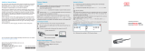
5.2 Electrical Connections
5.2.1 General
Fig. 10 Arrangement of connections
Power Power supply connection
Data Gigabit Ethernet connection
I/O Multi-function connection
5.2.2 Supply Voltage (Power)
The power supply connection in the form of a 4-pin M12 round connector has a current carrying capacity of up to 2 A per
pin.
Designation Pin no. Cable color ECR3000-x Notes Connection view
+U
B
1 Brown 18 V ... 30 V DC
(rated value 24 V)
1 2
4 3
View: Plug on housing side
+U
B
2 White
GND 3 Blue
0 V
GND 4 Black
Screen Housing
Fig. 11 Pin assignment of the power supply connection
The operating voltage is protected against polarity reversal. Use only shielded lines or original cables from the accesso-
ries program for the power supply connection or the outputs.
Micro-Epsilon recommends the ECR3000-x shielded supply cable.

Seite 17
Installation and Mounting
surfaceCONTROL 3D 35xx
5.2.3 Gigabit Ethernet Connection
The Ethernet connection is the standard connection to the PC. The sensor supports transmission at 1 Gbit/s.
An 8-pin X-coded M12 socket is installed in the housing.
RJ-45 connector 8-pin X-coded socket (housing side)
Pin no.
Color of stranded
hook-up wire
Pin no. 100BaseTX 1000BaseTX
1 White (orange) 1 Tx+ D1+
2 Orange 2 Tx- D1-
3 White (green) 3 Rx+ D2+
4 Blue 8 D3+
5 White (blue) 7 D3-
6 Green 4 Rx- D2-
7 White (brown) 5 D4+
8 Brown 6 D4-
1
View on pin side of male cable
connector
1 8
4 5
2 7
3 6
View: Socket on housing side
Fig. 12 Pin assignment of Gigabit Ethernet connection according to IEC 61076-2-109
For use with an Ethernet connection, we recommend the SCR3000X-x Gigabit Ethernet connection cable; cable length x
in meters. Characteristics: 4 x 2 x 0.14 mm²; shielded.
Due to the high data rate, we recommend a high-quality Ethernet PC plug-in card, for example, Intel-Pro/1000 PT. Pref-
erably the sensors should be connected directly to the network connection or using a high-quality switch. A hub would
cause massive data collisions and may not be used. On the PC, one or more network cards should always be intended
solely for the sensors.
Operating the sensors via Ethernet requires no additional driver installation. However, the network settings must be spec-
ified correctly:
- The sensor supports DHCP. This setting is enabled by default and has priority over searching in the link local network.
- A fixed IP address can be assigned.
- Various network settings (e.g. firewall or packet filters) can interfere with communications with the sensor.
- The sensor supports jumbo frames up to 9014 bytes/packet; however, in that case all network components must also
support jumbo frames up to that size.

Seite 18
Installation and Mounting
surfaceCONTROL 3D 35xx
5.2.4 Multi-Function Connection I/O
Interfaces and signals for external control of the sensor or for outputting sensor states and data are provided via the
multi-function connection. The four connections operate either as inputs or outputs.
Designation Pin no. Cable color PCR3000-x Notes Connection view
reserved 9 Red
1
10
11
12
2 3
4
5
6
7
8
9
View: Socket, housing side
reserved 2 Blue
reserved 3 White
reserved 1 Brown
reserved 12 Red-blue
reserved 11 Gray-pink
reserved 10 Purple
GPIO1 4 Green
General purpose IO 1
hardware trigger
GPIO2 6 Yellow General purpose IO 2
GPIO3 8 Gray General purpose IO 3
GPIO4 5 Pink General purpose IO 4
GND GPIO 7 Black Ground connection GPIO
Screen Housing Not electrically connected to GND GPIO
Fig. 13 Pin assignment of the multi-function connection
The multi-function connection is a 12-pin M12 round connector. The connecting line is intended to be up to 35 m long;
however, the cable must be shielded at any length. Micro-Epsilon recommends using the PCR3000-x multi-function
cable.
5.2.4.1 Digital Signals
The four digital connections of the multi-function interface provided can operate optionally as inputs or outputs. They are
configured using the software. All digital ports share a joint ground GND GPIO.
External auxiliary power (max. 30 V) is required to use the outputs.
The digital signals are not suitable for brief signal pulses or time-critical signals. The exception is port 1, which, when
configured correctly, can be used as a hardware trigger to start a measurement and is directly connected to the se-
quence control in the sensor.
The functionality of the digital signals can be programmed, see Fig. 14. In addition to direction, polarity can also be
switched for the inputs and outputs. Internal sensor signals can be assigned to the digital outputs, for example, to con-
trol additional connected devices.
Inverter selection
(software side)
Direction selection
(software side)
Output signal selection
(software side)
(Output) Line 1
Trigger/GPIO1
(Output) Line 2
GPIO2
(Output) Line 3
GPIO3
(Output) Line 4
GPIO4
false
true
(IO) Line 1
false
true
(IO) Line 2
false
true
(IO) Line 3
false
true
(IO) Line 4
Input
Output
Input
Output
Input
Output
Input
Output
FrameTriggerWait
FrameTriggerMissed
ExposureActive
FrameActive
HardwareError
UserOutput0
Fig. 14 Programmable inputs and outputs

Seite 19
Installation and Mounting
surfaceCONTROL 3D 35xx
The outputs can optionally be assigned the internal signals below:
Internal signal Description
UserOutput0 Digital output signal that can be set via Genicam
FrameTriggerWait Sensor is ready for next measurement
FrameTriggerMissed (External) trigger was missed
(sensor was not yet ready for measurement)
FrameActive 3D measurement in sensor is active
(start at exposure of first image, end at completion of data transmission via GigE)
ExposureActive Image sequence recording is enabled for current frame
(start at first image, end at last image transmission)
HardwareError Critical error in sensor: Hardware error or sensor has become too hot.
Fig. 15 Internal signal for digital outputs
5.2.4.2 Electrical Parameters of Digital Inputs, Multi-Function Connection
The switching levels of the digital inputs are defined based on HTL logic:
Low 0 … 3 V, High 11 … 24 V (up to 30 V permitted). Maximum input current is internally limited to 5 mA.
The GPIO_1 input can also be used as a trigger signal. The minimum pulse duration when used as a trigger signal is
50 µs. Switching delay until a measurement is triggered is at most 10 µs.
0 V
11 V
U
IN, high
U
t
delay trigger
t
start active
trigger
All inputs can be used as logical inputs, but not for time-critical tasks.
GND GPIO
DRV
Customer Device Sensor

Seite 20
Installation and Mounting
surfaceCONTROL 3D 35xx
5.2.4.3 Electrical Parameters of Digital Outputs, Multi-Function Connection
The digital outputs require an external auxiliary voltage between 5 V and 30 V as well as load resistance. They can be
operated at a load current of at most 100 mA. This may occur, for example, by using an NPN-switching input module of a
control.
The outputs are switched using a SolidState relay and are low active.
GND GPIO
VCC GPIO
R
L
Customer DeviceSensor
I
Out
Fig. 16 Example for the timing behavior of an output at VCC GPIO = 24 V, I
Out
= 10 mA, R
L
= 2.4 kW
0 V
24 V
U
t
on
t
off
t
duration
t
t
on
< 0.1 ms
t
off
< 1.0 ms
Fig. 17 Switching times of digital output
5.3 Installation Instructions
For all connection cables, use only the appropriate cables from the optional accessories.
Tighten the cable connectors. The recommended tightening/screwing torque is at most 1.0 Nm.
Do not apply force when tightening.
> Damage to or destruction of the sensor
Lay all connection cables in accordance with the generally applicable measuring technology regulations, i.e. for example
not directly next to pulse-carrying lines, preferably in a separate cable duct.
Never bend the cables more tightly than the minimum bending radii.
MICRO-EPSILON recommends using the optionally available power supply PS2020, installation of top-hat rail,
input 230 VAC, output 24 VDC/2.5 A, see Appendix.
5.4 Commissioning
The sensor may only be connected to peripherals when it does not carry power, that is, only when the
operating voltage has been switched off.
Mount the sensor according to the installation instructions, see Chap. 5.1.
Connect the sensor to the Ethernet cable.
Connect the Ethernet cable to the PC.
Connect the sensor to the power supply.
/