Page is loading ...

MICRO-EPSILON MESSTECHNIK GmbH & Co. KG
Koenigbacher Str. 15 · 94496 Ortenburg / Germany
Tel. +49 (0) 8542 / 168-0 · Fax +49 (0) 8542 / 168-90
[email protected] · www.micro-epsilon.com
Your local contact: www.micro-epsilon.com/contact/worldwide/
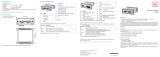
Operating Instructions
C-Box/2A

MICRO-EPSILON
MESSTECHNIK
GmbH & Co. KG
Koenigbacher Str. 15
94496 Ortenburg / Germany
Tel. +49 (0) 8542 / 168-0
Fax +49 (0) 8542 / 168-90
www.micro-epsilon.com
Controller for ILD 1420, ILD 1750, ILD 1900, ILD 2300 and confocalDT IFC2422 series

C-Box/2A
Contents
1. Safety ........................................................................................................................................ 7
1.1 Symbols Used ................................................................................................................................................. 7
1.2 Warnings .......................................................................................................................................................... 7
1.3 Notes on CE Marking ...................................................................................................................................... 8
1.4 Intended Use ................................................................................................................................................... 8
1.5 Proper Environment ......................................................................................................................................... 8
2. Functional Principle, Technical Data ...................................................................................... 9
2.1 Functional Principle ........................................................................................................................................ 9
2.2 Technical Data ............................................................................................................................................... 10
3. Delivery ................................................................................................................................... 12
3.1 Unpacking, Included in Delivery.................................................................................................................... 12
3.2 Storage .......................................................................................................................................................... 12
4. Installation and Mounting ...................................................................................................... 13
4.1 Dimensional Drawing ..................................................................................................................................... 13
4.2 Electrical Connections, LEDs ........................................................................................................................ 14
4.3 Laser on ......................................................................................................................................................... 16
5. Operation ................................................................................................................................ 17
5.1 Getting Ready for Operation ......................................................................................................................... 17
5.2 Installation of USB Driver ............................................................................................................................... 17
5.3 Software Update ............................................................................................................................................ 19
5.4 Operation Using Ethernet .............................................................................................................................. 20
5.4.1 Requirements ............................................................................................................................... 20
5.4.2 Access via Ethernet ...................................................................................................................... 20
5.4.3 Measured Value Presentation with Web Browser ........................................................................ 26
5.5 Programming Using ASCII Commands ........................................................................................................ 29
5.6 Timing Behavior, Flow of Measurement Values ............................................................................................ 29

C-Box/2A
6. Setting Controller Parameters ............................................................................................... 30
6.1 Preparation for Setting the Options ............................................................................................................... 30
6.2 General Overview .......................................................................................................................................... 30
6.3 Inputs ............................................................................................................................................................. 31
6.3.1 Sensor 1, Sensor 2 ....................................................................................................................... 31
6.3.2 Digital Input ................................................................................................................................... 37
6.4 Data Recording .............................................................................................................................................. 38
6.4.1 Measurement Task ....................................................................................................................... 38
6.4.2 Measuring Rate ............................................................................................................................ 39
6.4.3 Error Handling .............................................................................................................................. 40
6.5 Processing ..................................................................................................................................................... 41
6.5.1 Filter/Averaging ............................................................................................................................ 41
6.5.2 Mastering/Zeroing ........................................................................................................................ 42
6.5.3 Trigger Mode ................................................................................................................................ 42
6.5.4 Synchronization ............................................................................................................................ 44
6.5.5 Output Data Rate .......................................................................................................................... 44
6.6 Outputs .......................................................................................................................................................... 45
6.6.1 Digital Interface Selection ............................................................................................................. 45
6.6.2 Data Selection Ethernet and Data Selection USB ....................................................................... 46
6.6.3 Settings Ethernet .......................................................................................................................... 47
6.6.4 Settings USB ................................................................................................................................ 48
6.6.5 Digital Outputs .............................................................................................................................. 48
6.6.6 Analog Output 1, Analog Output 2 ............................................................................................... 50
6.7 System Settings ............................................................................................................................................. 51
6.7.1 Unit, Language ............................................................................................................................. 51
6.7.2 Save Settings ................................................................................................................................ 52
6.7.3 Load Settings ................................................................................................................................ 52
6.7.4 Manage Settings on PC ............................................................................................................... 53
6.7.5 Reset ............................................................................................................................................. 54
6.8 Info ................................................................................................................................................................. 54
7. Software Support with MEDAQLib ........................................................................................ 55
8. Liability for Material Defects .................................................................................................. 56
9. Service, Repair ....................................................................................................................... 56
10. Decommissioning, Disposal ................................................................................................. 56

C-Box/2A
Appendix
A 1 Accessories ............................................................................................................................ 57
A 2 ASCII Communication with Sensor ....................................................................................... 60
A 2.1 General .......................................................................................................................................................... 60
A 2.2 Data Protocol ................................................................................................................................................. 60
A 2.3 Commands Overview .................................................................................................................................... 65
A 2.3.1 General Commands ..................................................................................................................... 67
A 2.3.1.1 Controller Information ................................................................................................. 67
A 2.3.1.2 Search Sensor ............................................................................................................. 67
A 2.3.1.3 Sensor Information ...................................................................................................... 68
A 2.3.1.4 Read All Settings ......................................................................................................... 68
A 2.3.1.5 Language Setting ........................................................................................................ 68
A 2.3.1.6 Synchronization........................................................................................................... 69
A 2.3.1.7 Booting the Controller ................................................................................................. 69
A 2.3.2 Triggering ...................................................................................................................................... 69
A 2.3.2.1 Trigger Selection ......................................................................................................... 69
A 2.3.2.2 Trigger Level ................................................................................................................ 70
A 2.3.2.3 Number of Measuring Values Displayed .................................................................... 70
A 2.3.2.4 Software Trigger Pulse ................................................................................................ 70
A 2.3.3 Interfaces ...................................................................................................................................... 71
A 2.3.3.1 Ethernet ....................................................................................................................... 71
A 2.3.3.2 Setting the Measured Value Server ............................................................................ 71
A 2.3.3.3 Baudrate ...................................................................................................................... 71
A 2.3.3.4 Find C-Box/2A ............................................................................................................ 71
A 2.3.4 Handling of Setups ....................................................................................................................... 71
A 2.3.4.1 Save Parameter ........................................................................................................... 71
A 2.3.4.2 Load Parameter ........................................................................................................... 72
A 2.3.4.3 Default Settings ........................................................................................................... 72
A 2.3.5 Measurement ................................................................................................................................ 72
A 2.3.5.1 Measurement Mode .................................................................................................... 72
A 2.3.5.2 Measuring Rate ........................................................................................................... 72
A 2.3.5.3 Measured Value Averaging Controller ........................................................................ 73
A 2.3.5.4 Measured Value Averaging Sensor............................................................................. 73
A 2.3.5.5 Setting Masters / Zero ................................................................................................. 73

C-Box/2A
A 2.3.6 Data Output .................................................................................................................................. 74
A 2.3.6.1 Selection Digital Output .............................................................................................. 74
A 2.3.6.2 Output Data Rate ......................................................................................................... 74
A 2.3.6.3 Scale Output Values .................................................................................................... 74
A 2.3.6.4 Error Processing ......................................................................................................... 75
A 2.3.6.5 Data Selection for USB ............................................................................................... 75
A 2.3.6.6 Data Selection for Ethernet ......................................................................................... 76
A 2.3.6.7 Function Selection Multifunctional Input ..................................................................... 77
A 2.3.6.8 Activate Error Output, Switching Output 1 .................................................................. 77
A 2.3.6.9 Activate Error Output, Switching Output 2 .................................................................. 78
A 2.3.6.10 Limit Values ................................................................................................................. 78
A 2.3.6.11 Data Selection ............................................................................................................ 79
A 2.3.6.12 Output Range .............................................................................................................. 79
A 2.3.6.13 Two-point Scaling ........................................................................................................ 80
A 2.3.6.14 Send Command to Connected Sensor ...................................................................... 81
A 2.3.7 Laser ............................................................................................................................................. 81
A 2.3.7.1 Laser off / Laser on ...................................................................................................... 81
A 2.3.8 Error Values .................................................................................................................................. 82
A 2.3.8.1 Error Values via USB ................................................................................................... 82
A 2.3.8.2 Error Values via Ethernet ............................................................................................. 82
A 3 Control Menu .......................................................................................................................... 83
A 3.1 Tab Home ....................................................................................................................................................... 83
A 3.1.1 Input .............................................................................................................................................. 83
A 3.1.2 Measurement Configuration ......................................................................................................... 84
A 3.1.3 System Configuration ................................................................................................................... 85
A 3.1.4 Data Selection .............................................................................................................................. 85
A 3.2 Tab Settings ................................................................................................................................................... 86
A 3.2.1 Inputs ............................................................................................................................................ 86
A 3.2.2 Data Recording ............................................................................................................................. 87
A 3.2.3 Processing .................................................................................................................................... 88
A 3.2.4 Outputs ......................................................................................................................................... 90
A 3.2.5 System Settings ............................................................................................................................ 92
A 3.3 Tab Measurement .......................................................................................................................................... 93
A 3.3.1 Measurement Configuration ......................................................................................................... 93
A 3.3.2 Channel Selection ........................................................................................................................ 93
A 3.3.3 Auto Zero ...................................................................................................................................... 93
A 3.4 Tab Info .......................................................................................................................................................... 94

Page 7
Safety
C-Box/2A
1. Safety
System operation assumes knowledge of the operating instructions.
1.1 Symbols Used
The following symbols are used in these operating instructions:
Indicates a hazardous situation which, if not avoided, may result in minor or moder-
ate injury.
Indicates a situation that may result in property damage if not avoided.
Indicates a user action.
i
Indicates a tip for users.
1.2 Warnings
Connect the power supply and the display/output device according to the safety regulations for electrical
equipment.
> Risk of injury
> Damage to or destruction of the controller
The supply voltage must not exceed the specified limits.
> Damage to or destruction of the controller
Avoid shocks and impacts to the controller.
> Damage to or destruction of the controller

Page 8
Safety
C-Box/2A
1.3 Notes on CE Marking
The following apply to the C-Box/2A:
- EU Directive 2014/30/EU
- EU Directive 2011/65/EU, “RoHS“
Products which carry the CE mark satisfy the requirements of the EU directives cited and the relevant appli-
cable harmonized European standards (EN). The controller is designed for use in industrial environments.
The EU Declaration of Conformity is available to the responsible authorities according to EU Directive, article
10.
1.4 Intended Use
- The C-Box/2A is designed for industrial use in automated manufacturing and machine monitoring. It is
used for
processing 2 digital input signals, e. g. thickness measurement
filtering of measurements
- The controller must only be operated within the limits specified in the technical data, see 2.2.
- The system must be used in such a way that no persons are endangered or machines and other material
goods are damaged in the event of malfunction or total failure of the system.
- Take additional precautions for safety and damage prevention in case of safety-related applications.
1.5 Proper Environment
- Protection class: IP40
1
- Temperature range:
Operating: +5 ... +50 °C (+41 ... +122 °F)
Storage: 0 ... +50 °C (+32 ... +122 °F)
- Humidity: 5 - 95 % (non condensing)
- Ambient pressure: Atmospheric pressure
i
The protection class is limited to water (no penetrating liquids or similar).
1) Only with sensor cable connected.

Page 9
Functional Principle, Technical Data
C-Box/2A
2. Functional Principle, Technical Data
2.1 Functional Principle
The C-Box/2A is used for processing two digital input signals.
Features:
- Processing of 2 input signals
- Programmable via Ethernet (web pages)
- Semi-automatic sensor detection for MICRO-EPSILON sensors with digital output
- Triggering
- Ethernet interface with TCP and UDP protocols
- USB interface
- D/A converter of the digital measurements, output via current and voltage interface
The C-Box/2A is installed in a stable aluminium case.
Two digital sensors of the same series can be directly connected to the C-Box/2A via RS422.
Both sensors are synchronized via the C-Box/2A; the C-Box/2A is the master.
The parameterization of all inputs and outputs on the C-Box/2A is performed via a Web interface.
An internal time base also enables the calculation of measurement results of different measuring frequencies.

Page 10
Functional Principle, Technical Data
C-Box/2A
2.2 Technical Data
Model C-Box/2A
Connections
- 2 Sensor connectors (HD-Sub, 15-pin),
- 2 RS422 interfaces
- 1x Ethernet (PC, 100 Mbit/s),
- 1x USB 2.0, type B, max. 12 Mbit,
- 1 plug-in terminal block 16-pin
External power supply
External laser on/off
External trigger input
2 analog outputs (current or voltage)
- 1 external multi function input
- 1 external trigger input, HTL and TTL compatible (measurement output,
edge)
- Input voltage
TTL ≤ 0.7 V / HTL ≤ 3.0 V > trigger not active
TTL > 2.2 V / HTL > 8.0 V > trigger active
- input current 3.0 mA max.
- input frequency 100 kHz max.
- 2 switching outputs
Supported sensors
Sensors of the ILD 1420 series with a measuring rate of 0.25 ... 4 kHz, sen-
sors of the ILD 1750 series with a measuring rate of 0.3 ... 7.5 kHz, sensors
of the ILD 1900 series with a measuring rate of 0.25 ... 10 kHz and sensors
of the ILD 2300 series with a measuring rate of 1.5 … 49 kHz
Functions
Filter: average moving 2…512 / recursive 2…32768, Median 3,5,7,9
Zero, mastering, synchronization
Scaling analog outputs

Page 11
Functional Principle, Technical Data
C-Box/2A
Model C-Box/2A
Analog output
- 1 current output per connected sensor
4 – 20 mA
- 1 voltage output per connected sensor; programmable:
Unipolar 0 – 5 V / Unipolar 0 – 10 V
Bipolar ± 5 V / Bipolar ± 10 V
- Tolerance of current and voltage output: 0.04 %
Laser switch off
- Switch respectively voltage input:
switching input connected with > laser = on
switching input open > laser = off
input voltage < 3 V (HTL) > laser = on
input voltage > 8 V (HTL) > laser = off
Firmware
Measurement configurations can be saved (max. 8)
two languages (English, German), can be updated
LED For successful connection controller/sensor, Ethernet
Power supply
- 13 – 30 VDC for full functionality, power consumption max. 200 mA
without sensor
- 10 – 13 VDC with reduced DA converter function, power consumption
max. 200 mA without sensor, analog output 0 - 5 V or ± 5 V only
- Reverse polarity protection
- No galvanic isolation, all GND signals are connected internally and with
the housing
Power consumption sensors Maximum two sensors from internal power supply
Weight Appr. 210 g
Case dimensions Appr. 103 x 39 x 106 mm
Protection class IP40

Page 12
Delivery
C-Box/2A
Model C-Box/2A
Temperature range
Operating +5 ... +50 °C (+41 ... +122 °F)
Storage 0 ... +50 °C (+32 ... +122 °F)
Relative air humidity 5 ... 95 %, non-condensing
3. Delivery
3.1 Unpacking, Included in Delivery
1 C-Box/2A
1 Operating instructions
1 16-pin. female terminal box (cable clamp) with locking function type
Weidmüller B2CF 3.50/16/180 SN BK BX
Carefully remove the components of the measuring system from the packaging end ensure that the
goods are forwarded in such a way that no damage can occur.
Check for completeness and transport damage immediately after unpacking.
In case of damage or missing parts, please contact the supplier immediately.
3.2 Storage
Temperature range storage: 0 ... +50 °C (+41 ... +122 °F)
Humidity: 5 - 95 % (non-condensing)

Page 13
Installation and Mounting
C-Box/2A
4. Installation and Mounting
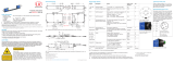
4.1 Dimensional Drawing
i
Pay attention to careful handling during
the installation and operation.
Status 1
Status 2
Sensor 2Sensor 1
C-Box/2A
102.9 (4.05)
40 (1.57)
90 (3.54)
110.8 (4.36)
Fig. 1 Dimensions C-Box/2A, dimensions in mm (inches), not to scale

Page 14
Installation and Mounting
C-Box/2A
4.2 Electrical Connections, LEDs
1
1
2 2
Pin Signal
1 RS422 TxD-
2 RS422 TxD+
3 RS422 RxD-
4 RS422 RxD+
5 GND
6 RS422 TRG+
7 RS422 TRG-
8 5V CMOS output (reserve, do not connect)
9 Power supply +24 V via power connection
10 Power supply +24 V via power connection
11 Multfunction output TTL or HTL compatible
12 Laser on, HTL compatible
13 NC
14 NC
15 GND
Fig. 2 Pin assignment sensor connector (2), sensor 1 resp. sensor 2
LED color Description
Off Sensor not connected
Green Sensor in measurement mode and within the measurement range
Red Sensor in measurement mode and sensor outside the measurement range
Orange Sensor in setup mode (no measurement output)
Fig. 3 Description LED (1) for sensor 1 resp. sensor 2

Page 15
Installation and Mounting
C-Box/2A
3
4
Pin Designation Signal
1 24VDC Power
2 GND GND
3 TRG IN Trigger in
4 MF IN Multi function input
5 OUT S1 Switching output 1
6 Laser Laser
7 OUT S2 Switching output 2
8 GND GND
9 OUT V1 Measurement value voltage 1
10 GNDA Analog GND1
11 OUT I1 Measurement value current 1
12 Shield Schirm
13 OUT V2 Measurement value voltage 2
14 GNDA Analog GND2
15 OUT I2 Measurement value current 2
16 Shield Schirm
Fig. 4 Pin assignment 16-pin terminal block (4), type Weidmüller (B2CF)
LED color Description
Off no power supply (power off)
Green
Power on, data output on USB interface not active or
data output on USB interface active and data communication error free
Orange
Power on, data output on USB interface active,
data communication faulty or disconnected
Red
Power on, data output on USB interface active,
USB cable not connected or communication disconnected
Fig. 5 LED description for power and USB status (3)

Page 16
Installation and Mounting
C-Box/2A
4.3 Laser on
Fig. 6 View Settings - Inputs - Sensor 1/2 - Laser
The measuring laser on the sensor is activated via an optocoupler input. This is advantageous if the sensor has to be switched off for
maintenance or similar. Switching can be done with a transistor (for example open collector in an optocoupler) or a relay contact.
Connect pin 6 Laser with pin 8 GND by a jumper.
i
The laser is off unless pin 6 is electrically connected to pin 8.

Page 17
Operation
C-Box/2A
5. Operation
5.1 Getting Ready for Operation
The C-Box/2A must be installed in accordance with the installation instructions, see 4, and connected to an
automation unit, e.g. PLC, and the power supply in compliance with the connection instructions.
After switching on the operating voltage, the C-Box/2A performs an initialization sequence and goes into the
measurement operating mode afterwards.
The laser operation on optical sensors is only indicated at the sensor by an LED. If no measured values are
transmitted, check whether the sensors are switched on and whether a target is in the measuring range of the
sensor.
5.2 Installation of USB Driver
You will find the driver C-Box/2A WinUSB under:
www.micro-epsilon.de/link/software/medaqlib
Connect C-Box/2A to the usb port of your computer.
Connect C-Box/2A to power supply.
Open Windows system control.
Go to device manager.
You will see a device with a question mark (unknown device).
Right mouse click on it.
A menu opens.
Select Properties.
Select Drivers.
Select Update driver.
Browse to the directory with the downloaded Win usb drivers.
Click on ok.
Wait until installation will finish.


Page 19
Operation
C-Box/2A
5.3 Software Update
i
The software can only be updated via USB.
Download the USB driver from the homepage, see 5.2 and unpack it.
Start the installation program.
Search for the C-Box.
Choose the update file.
Start the installation.
Wait until the installation is complete.
Fig. 8 View MICRO-Epsilon Update Sensor

Page 20
Operation
C-Box/2A
5.4 Operation Using Ethernet
Dynamic web pages are generated in the C-Box/2A which contain the current settings of the C-Box/2A and the peripherals. The op-
eration is only possible while there is an Ethernet connection to the C-Box/2A.
5.4.1 Requirements
You need a web browser (e.g. Mozilla Firefox or Internet Explorer) on a PC with a network connection. Decide about connecting the
C-Box/2A to a network or directly to a PC.
The C-Box/2A is delivered as standard with a fixed IP address. If you do not require a static IP address, you can enable DHCP (Dy-
namic Host Configuration Protocol) as automatic IP address allocation. The controller will be assigned an IP address by the DHCP
server, see 5.4.2.
If you have set your browser so that it accesses internet through a proxy server, please add the IP address of the controller to the IP
addresses that should not be routed through the proxy server in the settings of the browser.
Parameter Description
Address type Static IP address (standard) or dynamic IP address (DHCP, Standard)
IP address Static IP address of the controller (only active if no DHCP is selected).
Gateway Gateway to the other subnets
Subnet mask Subnet mask of the IP subnet
Fig. 9 Basic Ethernet settings
5.4.2 Access via Ethernet
Direct connection to PC, controller with static IP (Factory setting) Network
PC with static IP PC with DHCP Controller with dynamic IP, PC with DHCP
Connect the C-Box/2A („Ethernet“ female connector) with a PC via an Ether-
net direct connection (LAN). Use a LAN cable with RJ-45 connectors for this.
Connect the controller with a switch
(Intranet). Use a LAN cable with RJ-45 con-
nectors.
/