Page is loading ...

Page 1
surfaceCONTROL 3D 35xx
Assembly Instructions
surfaceCONTROL 3D 35xx
1. Warnings
Do not look directly into the light source of the sensor.
> Risk of injury, damage to the eyes and skin
Connect the power supply and the display/output device according to the safety
regulations for electrical equipment.
> Risk of injury
> Damage to or destruction of the sensor
Avoid shocks and impacts to the sensor.
The supply voltage must not exceed the specified limits.
Avoid constant exposure of the sensor to dust or splashes of water by appropriate
methods such as blowing or using a protective housing.
The sensor housing may only be opened by authorized persons.
> Damage to or destruction of the sensor
Do not touch the protective windows of the optics. Wipe off any fingerprints
immediately with pure alcohol and a clean cotton cloth with no streaks. Protect the
cables against damage.
> Failure of the measuring device
Do not plug or unplug devices during the operation.
2. Notes on CE Marking
The following apply to the surfaceCONTROL 3D 35xx:
- EU Directive 2014/30/EU
- EU Directive 2011/65/EU
Products which carry the CE mark satisfy the requirements of the EU directives cited
and the relevant applicable harmonized European standards (EN). The measuring
system is designed for use in industrial environments.
The EU Declaration of Conformity and the technical documentation are available to the
responsible authorities according to the EU Directives.

Page 2
surfaceCONTROL 3D 35xx
3. Proper Environment
- Protection class
Sensor: IP67 (only applies in the case of connected output connectors
and/or installed protective caps)
Optical paths during operation are excluded from the protection class.
Contamination of the paths causes impairment or failure of the function.
The IP67 protection class is a specification that is limited to protection from dust and
water. Oil, steam and emulsion effects are not included in this protection class and
must be evaluated separately.
- Temperature range
Operation: 0 ... +45 °C
1
(+32 ... +113 °F)
Storage: -20 ... +70 °C (-4 ... +158 °F)
- Humidity: 20 ... 80 % (non condensing)
- Ambient pressure: Atmospheric pressure
1) Max. permissible operating temperature depends on installation scenario, thermal
connection and operating mode. If necessary, external heat dissipation must be used to
ensure that the sensor’s internal temperature of 60 °C is not exceeded.
4. Delivery surfaceCONTROL 3D 35xx
- 1 Sensor surfaceCONTROL 3D 35xx
- 1 Assembly instructions
- 1 Calibration final inspection
- 3 Protective caps
- 1 ECR3000-5 supply cable 5 m
- 1 SCR3000X-5 Ethernet interface cable 5 m
Carefully remove the components of the measuring system from the packaging
and ensure that the goods are forwarded in such a way that no damage can occur.
Check the delivery for completeness and shipping damage immediately after
unpacking.
If there is damage or parts are missing, immediately contact the manufacturer or
supplier.

Page 3
surfaceCONTROL 3D 35xx
5. Light Source
The surfaceCONTROL 3D 35xx sensor works with an LED lighting unit. Measurement is
performed using blue light at the dominant 459 nm wavelength. The sensor is included
in risk group 2 according to EN 62471: 2008.
Do not look into the lens. Consciously close your eyes or immedi-
ately turn away if the optical radiation enters the eye.
The warning sign below is attached to the sensor housing on the top and bottom:
Fig. 1 LED warning sign
i
If both warning labels are covered over when the unit is installed, the user must
ensure that supplementary labels are applied.

Page 4
surfaceCONTROL 3D 35xx
6. Electrical Connections
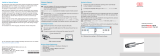
Fig. 2 Arrangement of connections
Power Supply voltage
Data Gigabit Ethernet connection
I/O Multi-function connection
Supply Voltage (Power)
The power supply connection in the form of a 4-pin M12 round connector has a current
carrying capacity of up to 2 A per pin.
Designation Pin no.
Cable color
ECR3000-x
Notes
Connection view
+U
B
1 Brown 18 V ... 30 V DC
(rated value 24 V)
1 2
4 3
View: Plug on
housing side
+U
B
2 White
GND 3 Blue
0 V
GND 4 Black
Screen Housing
Fig. 3 Pin assignment of the power supply connection
The operating voltage is protected against polarity reversal. Use only shielded lines or
original cables from the accessories program for the power supply connection or the
outputs.
Micro-Epsilon recommends the ECR3000-x shielded supply cable.

Page 5
surfaceCONTROL 3D 35xx
Multi-Function Connection I/O
Interfaces and signals for external control of the sensor or for outputting sensor states
and data are provided via the multi-function connection. The four connections operate
either as inputs or outputs.
Designation Pin no.
Cable color
PCR3000-x
Notes Connection view
reserved 9 Red
1
10
11
12
2 3
4
5
6
7
8
9
View: Socket,
housing side
reserved 2 Blue
reserved 3 White
reserved 1 Brown
reserved 12 Red-blue
reserved 11 Gray-pink
reserved 10 Purple
GPIO1 4 Green
General purpose IO 1
hardware trigger
GPIO2 6 Yellow General purpose IO 2
GPIO3 8 Gray General purpose IO 3
GPIO4 5 Pink General purpose IO 4
GND GPIO 7 Black Ground connection GPIO
Screen Housing Not electrically connected to GND GPIO
Fig. 4 Pin assignment of the multi-function connection
The multi-function connection is a 12-pin M12 round connector. The connecting line
is intended to be up to 35 m long; however, the cable must be shielded at any length.
Micro-Epsilon recommends using the PCR3000-x multi-function cable.

Page 6
surfaceCONTROL 3D 3500
Digital Signals
The four digital connections of the multi-function interface provided can operate option-
ally as inputs or outputs. They are configured using the software. All digital ports share
a joint ground GND GPIO. External auxiliary power (max. 30 V) is required to use the
outputs.
The digital signals are not suitable for brief signal pulses or time-critical signals.
The exception is port 1, which, when configured correctly, can be used as a hardware
trigger to start a measurement and is directly connected to the sequence control in the
sensor.
The functionality of the digital signals can be programmed (see Fig. 5).
In addition to direction, polarity can also be switched for the inputs and outputs.
Internal sensor signals can be assigned to the digital outputs, for example, to control
additional connected devices.
Inverter selection
(software side)
Direction selection
(software side)
(Output) Line 1
Trigger/GPIO1
(Output) Line 2
GPIO2
(Output) Line 3
GPIO3
(Output) Line 4
GPIO4
false
true
(IO) Line 1
false
true
(IO) Line 2
false
true
(IO) Line 3
false
true
(IO) Line 4
Input
Output
Input
Output
Input
Output
Input
Output
Fig. 5 Programmable inputs and outputs

Page 7
surfaceCONTROL 3D 3500
The outputs can optionally be assigned the internal signals below:
Internal signal Description
UserOutput0 Digital output signal that can be set via Genicam
FrameTriggerWait Sensor is ready for next measurement
FrameTriggerMissed (External) trigger was missed
(sensor was not yet ready for measurement)
FrameActive 3D measurement in sensor is active (start at exposure of first
image, end at completion of data transmission via GigE)
ExposureActive Image sequence recording is enabled for current frame
(start at first image, end at last image transmission)
HardwareError Critical error in sensor: Hardware error or sensor has be-
come too hot.
Fig. 6 Internal signal for digital output
Output signal selection
(software side)
(Output) Line 1
Trigger/GPIO1
(Output) Line 2
GPIO2
(Output) Line 3
GPIO3
(Output) Line 4
GPIO4
FrameTriggerWait
FrameTriggerMissed
ExposureActive
FrameActive
HardwareError
UserOutput0

Page 8
surfaceCONTROL 3D 35xx
Electrical Parameters of Digital Inputs, Multi-Function Connection
0 V
11 V
U
IN, high
U
t
delay trigger
t
start active
trigger
The switching levels of the digital inputs are
defined based on HTL logic: Low 0 … 3 V,
High 11 … 24 V (up to 30 V permitted).
Maximum input current is internally limited
to 5 mA. The GPIO_1 input can also be
used as a trigger signal. The minimum pulse
duration when used as a trigger signal is
50 µs. Switching delay until a measurement
is triggered is at most 10 µs.
GND GPIO
DRV
Customer Device Sensor
All inputs can be used as logical inputs, but
not for time-critical tasks.
Electrical Parameters of Digital Outputs, Multi-Function Connection
The digital outputs require an external auxiliary voltage between 5 V and 30 V as well as
a load resistance. They can be operated at a load current of at most 100 mA. This may
occur, for example, by using an NPN-switching input module of a control.
The outputs are switched using a SolidState relay and are low active.
GND GPIO
VCC GPIO
Customer DeviceSensor
I
Out
R
L
0 V
24 V
U
t
on
t
off
t
duration
t
t
on
< 0.1 ms t
off
< 1.0 ms
Fig. 7 Example for the timing behavior of an
output at VCC GPIO = 24 V, I
Out
= 10 mA,
R
L
= 2.4 kW
Fig. 8 Switching times of digital output

Page 9
surfaceCONTROL 3D 35xx
7. LED Displays
LED LED Meaning
Fig. 9 LED displays
Off LED not active
Constant green LED active
LED State Meaning
Flashing orange Initialization of sensor hardware
Flashing green Initialization of communications interface
Constant green Sensor is ready for operation
Flashing
orange-green
Error during initialization of sensor hardware
Communication with sensor possible
Constant red Error during initialization
No communication with sensor possible
LED Power Meaning
Off No operating voltage or operating voltage
too low
Constant green Operating voltage applied
Constant red Error, operating voltage too high
LED Data
(Link / Act)
Meaning
Link LED (left):
Constant orange
Gigabit Ethernet connection established
Constant green
100 Mbit Ethernet connection established
Off
10 Mbit Ethernet connection established
Act LED (right):
Green
Active data transmission
Off
No data transmission
LED I/O
Meaning
reserved

Page 10
surfaceCONTROL 3D 35xx
8. Operation
Commissioning
The sensor may only be connected to peripherals when it does
not carry power, that is, only when the operating voltage has been
switched off.
Mount the sensor according to the installation instructions.
Connect the sensor to the Ethernet cable.
Connect the Ethernet cable to the PC.
Connect the sensor to the power supply.
Read the detailed operating instructions before operating the sensor.
These instructions are available online at www.micro-epsilon.com.
Turning On
Turn on the external DC voltage supply (24 VDC).
The Power LED is constantly illuminated green if sufficient operating voltage is applied.
The State LED flashes orange and green during hardware connection and initializa-
tion. After completion, it is constantly illuminated green. For more information, see the
“LED Displays” section, see Chap. 7.
i
The surfaceCONTROL 3D 35xx sensor requires a warm-up time of typically 60
minutes for precise measurements.
Operating Programs
Various programs are provided for operation of the sensor.
- 3D View visualizes in space three-dimensional point data that have been detected
with surfaceCONTROL 3D 35xx.
- 3DInspect solves industrial 3D measurement tasks.
- You can use surfaceCONTROL DefMap3D 7.0 for the analysis of individual surfaces
with surfaceCONTROL 3D 35xx.
9. Installation
Requirements
The following minimum system requirements are necessary for the operation of the
operating programs:
- Windows 8 or 8.1 (64 bit), Windows 10 (64 bit)
- 1-GHz or higher prozessor (64 bit) with 4 GB RAM
- Screen resolution: 1280 x 1024
- Graphic card / GPU with OpenGL 3.1 or higher
i
Connect the sensor directly to the PC. Do not use hubs.

Page 11
surfaceCONTROL 3D 35xx
10. Positioning of Sensor and Test Object
General
i
Note the following instructions for optimum positioning of the sensor and test
object.
- Observe an optimum distance between the sensor and the surface of the test object,
see Chap. 3.2.
- Align the sensor with predominantly diffusely reflecting surfaces almost perpendic-
ular to the surface. To avoid direct reflection, we recommend that you tilt the sensor
by a few degrees.
- In the case of partially glossy surfaces, reflections from the test object can be
reduced by inclining the sensor by up to 30° with respect to the surface of the test
object.
Alignment with Crosshair
You will achieve the best results in the mid of the measuring range (focal range of
cameras).
Use the positioning pattern to easily and optimally align the sensor in the mid of
the measuring range. Align the pattern of the projection with the superimposed
pattern.
Fig. 10 Result of camera images when aligned with crosshair
You will find further details
- in the respective operating instructions of the software provided by Micro-Epsilon,
- or in the sensors operating instructions, chapter GenICam parameter description.

MICRO-EPSILON MESSTECHNIK GmbH & Co. KG
Königbacher Str. 15 · 94496 Ortenburg / Deutschland
Tel. +49 (0) 8542 / 168-0 · Fax +49 (0) 8542 / 168-90
[email protected] · www.micro-epsilon.de
Your local contact: www.micro-epsilon.com/contact/worldwide/
X9771423-A022031MSC
11. Further Information
For details on the individual programs or on setting the sensor parameters, please
refer to the respective software operating manuals or the operating instructions of this
sensor.
12. Liability for Material Defects
All components of the device have been checked and tested for functionality at the
factory. However, if defects occur despite our careful quality control, MICRO-EPSILON
or your dealer must be notified immediately.
The liability for material defects is 12 months from delivery. Within this period, defec-
tive parts, except for wearing parts, will be repaired or replaced free of charge, if the
device is returned to MICRO-EPSILON with shipping costs prepaid. Any damage that
is caused by improper handling, the use of force or by repairs or modifications by third
parties is not covered by the liability for material defects. Repairs are carried out exclu-
sively by MICRO-EPSILON.
Further claims can not be made. Claims arising from the purchase contract remain
unaffected.
In particular, MICRO-EPSILON shall not be liable for any consequential, special, indirect
or incidental damage. In the interest of further development, MICRO-EPSILON reserves
the right to make design changes without notification.
For translations into other languages, the German version shall prevail.
13. Service, Repair
If the sensor or sensor cable is defective:
- If possible, save the current sensor settings
in a parameter set, see 3D-View, menu
Parameters > Save parameters to
file, in order to load the settings back
again into the sensor after the repair.
- Please send us the affected parts for repair
or exchange.
If the cause of a fault cannot be clearly
identified, please send the entire measuring
system to:
MICRO-EPSILON Optronik GmbH
Lessingstraße 14
01465 Langebrück / Germany
Tel. +49 (0) 35201 / 729-0
Fax +49 (0) 35201 / 729-90
www.micro-epsilon.com
/