Page is loading ...

MICRO-EPSILON MESSTECHNIK GmbH & Co. KG
Koenigbacher Str. 15
94496 Ortenburg / Germany
Tel. +49 8542 / 168-0 / Fax +49 8542 / 168-90
e-mail [email protected]
www.micro-epsilon.com
Assembly Instructions
wireSENSOR
WPS series
WPS-XXX-K100
X9771409-A022060HDR
*X9771409-A02*
Guiding and Attaching the Wire
If the measuring wire must be pulled out of the sensor to guide the wire or
attach it to the measured object:
- the sensor must not be held by a second person during that process,
- the measuring wire must not be pulled out beyond the measuring range
listed,
- the area around the sensor must be protected against snapping of the
measuring wire.
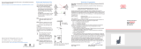
Fix the measuring wire to the
target using a wire clip.
Guide the measuring wire
vertically out of the sensor
housing.
Diagonal pull is only permitted up to
3 degrees.
If you drag the measuring wire over
the insertion hole or other objects,
the measuring wire will be damaged
and/or tear.
i
If the measuring wire cannot
be fed vertically out of the
housing, it is essential to use
a guide pulley (accessory
TR1-WDS or TR3-WDS, see
Operating instructions, chap-
ter Accessories).
Guide the measuring wire in a
protected area so that it cannot
get caught or otherwise be
damaged.
max. 3 °
Wire outlet 0 °
±3 ° tolerancy
Attachment and maximum diagonal-
pull of the measuring wire
You can download a PDF of detailed operating instructions from our website:
http://www.micro-epsilon.de/download/manuals/man--wireSENSOR-WPS-
K100--en.pdf
Declaration of Incorporation
Declaration of incorporation according to EC Machinery Directive 2006/42/EC,
Annex II B
The manufacturer and person authorized to compile the relevant technical docu-
ments
MICRO-EPSILON MESSTECHNIK GmbH & Co. KG
Königbacher Straße 15, 94496 Ortenburg / Germany
hereby declare that the machine designated below complies with the relevant
fundamental health and safety requirements of the EC Machinery Directive, including
modifications to it applicable at the time of this declaration, based on its design and
construction and in the version put on the market by us – to the extent that the scope
of supply allows.
Machine design: Draw-wire sensor
(mechanics and models with potentiometer output)
Type designation: WDS-xxx, WPS-xxx
The following fundamental health and safety requirements according to Annex I of
the directive specified above have been applied and complied with:
- No. 1.1.2. Principles of safety integration
- No. 1.7.3. Marking of machinery
- No. 1.7.4. Operating instructions
Furthermore, we declare compliance with the following directives and standards
including the modifications applicable at the time this declaration is made:
- Directive 2006/42/EC (machinery)
EN ISO 13857:2008 Safety of machinery - Safety distances to prevent hazard
zones being reached by upper and lower limbs
EN 60204-1: 2006 + EN 60204-1: 2006/A1: 2009 Safety of machinery - Electri-
cal equipment of machines - Part 1: General requirements
- Directive 2011/65/EU (RoHS)
EN 50581: 2012 Technical documentation for the assessment of electrical and
electronic devices with respect to the restriction of hazardous substances
We also declare that the special technical documentation for this partially completed
machine has been created in accordance with Annex VII, Part B, and commit our-
selves to disclose this to the market surveillance authorities upon request.
The commissioning of these partially completed machines is prohibited until the
partially completed machine(s) has/have been installed in a machine that meets
the requirements of the EC Machinery Directive and for which an EU Declaration of
Conformity according to Annex II, Part A exists.
Ortenburg, 22 May 2019 Dr. Thomas Wisspeintner
Managing Director
Current output (I) Integrated cable
-CA / -CR
Operating voltage 9 ... 32 VDC
(non-stabilized
1
)
White = Supply
Brown = Ground
Output current 4 ... 20 mA
Load < 600 Ohm
Output noise 1.6 µA
eff
Temperature coefficient ±0.005 % FSO/°C
Table for current output
FSO = Full Scale Output
1) Non-stabilized, measured on the input terminals of the sensor

Warnings
- Do not open the sensor housing.
- Do not pull or loop the measuring wire around unprotected body parts.
- Do not pull out the measuring wire beyond the measuring range listed.
- Do not let the measuring wire snap.
> Risk of injury
- Do not damage the measuring wire.
- Do not oil or grease the measuring wire.
- Do not kink the measuring wire.
- Do not pull the measuring wire diagonally.
- Do not let the measuring wire drag around objects.
- Attach the measuring wire to the measured object while the wire is retract-
ed.
> Damage to or destruction of the sensor
Proper Environment
- Sensor protection class: IP69K
- Temperature range
Operation: -40 ... +85 °C (-40 ... +185 °F)
Storage temperature: -40 ... +85 °C (-40 ... +185 °F)
- Humidity: 5 - 95 % (non-condensing)
- Ambient pressure: Atmospheric pressure
Unpacking/Included in Delivery
1 Sensor
4 Slot nuts
1 Assembly instructions
100 (3.94)
80 (3.15)
50 (1.97)
154.1 (6.07)
212 (8.35)
50 (1.97)
43
(1.69)
80 (3.15)
100 (3.94)
3x ø6.4
Mounting
grooves for M6
16.4 (.65)
82.5 (3.25)
52.2
38
(1.50)
Mounting
holes
15
(.60)
26
(1.02)
12
(.47)
Dimensional drawing WPS-3500-K100, WPS-5000-K100, dimensions in mm, not
to scale
Dimensional Drawings
26
(1.02)
38
(1.50)
52.2
(2.06)
82.5
(3.25)
15 (.60)
16.4 (.65)
100 (3.94)
80 (3.15)
50 (1.97)
104.1 (4.10)
162 (6.38)
50 (1.97)
43
(1.69)
80 (3.15)
100 (3.94)
3x ø6.4
Mounting grooves
for M6
Mounting
holes
12
(.47 )
Dimensional drawing WPS-1500-K100, WPS-2500-K100, dimensions in mm, not
to scale
Sensor Mounting
Mount the sensor either with M6 screws (through-hole) or with slot nuts
(mounting grooves) according to the specifications in the following table:
Model Screws for
through-hole
Slot nuts for
mounting grooves
WDS-1500-K100 3 x M6 M6 x 3.2 mm
WDS-2500-K100 3 x M6 M6 x 3.2 mm
WDS-3500-K100 3 x M6 M6 x 3.2 mm
WDS-5000-K100 3 x M6 M6 x 3.2 mm
The slot nuts can be mounted on each sensor side into the mounting grooves.
Make sure that the thread length of the screws, which you use for the slot nuts,
protrude from the sensor edge between 5 mm and 7 mm into the mounting
groove.
> Damage of the sensor housing due to the screw being too long
The sensor does not have to be oriented in a special way.
Select the installation position in such a way that damage to or contami-
nation of the measuring wire is avoided.
i
If possible, prefer an installation position in which the measuring wire
exits downward. This prevents liquids from entering the measuring wire
outlet.
i
Do not let the measuring wire snap! There is no liability for material
defects in case of damage due to snapping.
Electrical Data
Potentiometer output (P) Integrated cable
-CA / -CR
Input voltage max. 32 VDC with
1 kOhm / max. 1 W
White = Input +
Brown = Ground
Green = Signal
Resistance 1 kOhm ±10 %
(resistance divider)
Temperature coefficient ±0.0025 % FSO/°C
Contact current ≤10μA
Sensitivity dependent on
measuring range
Table of potentiometer output
FSO = Full Scale Output
Draw-wire displacement sensors with potentiometer output are connected
according to the table, see above. Use any potentiometer only when switched
to voltage divider. Using it as a variable resistor destroys the component.
Observe maximum contact currents.
i
Use potentiometers only as voltage dividers, not as variable series
resistors!
Voltage output (U) Integrated cable
-CA / -CR
Operating voltage 14 ... 27 VDC
(non-stabilized
1
)
White = Supply
Brown = Ground
Green = Signal
White = Supply
Current consumption max. 30 mA
Output voltage 0 ... 10 VDC
Options 0 ... 5 / ±5 V
Output current 2 mA max.
Load resistance > 5 kOhm
Output noise 0.5 mV
eff
Temperature coefficient ±0.005 % FSO/°C
Table for voltage output
FSO = Full Scale Output
1) Non-stabilized, measured on the input terminals of the sensor
/