Page is loading ...

surfaceCONTROL 2500-360 surfaceCONTROL 2500-360/ST
surfaceCONTROL 2500-500 surfaceCONTROL 2500-500/ST
surfaceCONTROL 2500-720 surfaceCONTROL 2500-720/ST
Operating Instructions
surfaceCONTROL 2500

INB Vision AG
Brenneckestr. 20
ZENIT Technology Park II
39118 Magdeburg / Germany
Tel. +49 (0) 391 / 6117-300
Fax +49 (0)391 / 6117-301
www.inb-vision.com

surfaceCONTROL 2500
Contents
1. Safety ........................................................................................................................................ 5
1.1 Symbols Used ................................................................................................................................................. 5
1.2 Warnings .......................................................................................................................................................... 5
1.3 Notes on CE Marking ...................................................................................................................................... 6
1.4 Intended Use ................................................................................................................................................... 6
1.5 Foreseeable Misuse ......................................................................................................................................... 6
1.6 Proper Environment ......................................................................................................................................... 7
2. llumination ................................................................................................................................ 7
3. Functional Principle, Technical Data ....................................................................................... 8
3.1 Short Description ............................................................................................................................................. 8
3.1.1 Measuring Principle ........................................................................................................................ 8
3.1.2 System Design ............................................................................................................................... 8
3.1.3 Particular Performance Characteristics .......................................................................................... 8
3.1.4 Other Advantages ........................................................................................................................... 8
3.2 Technical Data ................................................................................................................................................. 9
3.2.1 surfaceCONTROL 2500 .................................................................................................................. 9
3.2.2 surfaceCONTROL 2500/ST .......................................................................................................... 10
3.3 LED Indicators ............................................................................................................................................... 10
4. Delivery ................................................................................................................................... 11
4.1 Unpacking / Included in Delivery surfaceCONTROL 2500 ........................................................................... 11
4.2 Unpacking / Included in Delivery surfaceCONTROL 2500/ST ...................................................................... 11
4.3 Storage .......................................................................................................................................................... 11
5. Installation .............................................................................................................................. 12
5.1 Sensor ............................................................................................................................................................ 12
5.1.1 Dimensions ................................................................................................................................... 12
5.1.2 Mounting Adapters ....................................................................................................................... 13
5.1.2.1 General ........................................................................................................................ 13
5.1.2.2 Assembly with Flange Adapter .................................................................................. 13
5.2 Connectors .................................................................................................................................................... 14
5.2.1 surfaceCONTROL 2500 ................................................................................................................ 14
5.2.1.1 General ........................................................................................................................ 14
5.2.1.2 Supply Voltage (Power) ............................................................................................. 14
5.2.1.3 Sensor Control (USB) ................................................................................................ 14
5.2.1.4 Image Data Transmission (Gigabit Ethernet) ............................................................. 15
5.2.2 surfaceCONTROL 2500/ST .......................................................................................................... 16
5.2.2.1 General ........................................................................................................................ 16
5.2.2.2 Supply Voltage (Power) ............................................................................................. 16
5.2.2.3 Sensor Control (USB) ................................................................................................ 16
5.2.2.4 Image Data Transmission (Gigabit Ethernet) ............................................................. 16
5.2.3 Installation Instructions ................................................................................................................. 17
6. Operation of the Sensor ......................................................................................................... 18
6.1 Commissioning .............................................................................................................................................. 18
6.2 Displays ......................................................................................................................................................... 18
6.3 Operating Programs ...................................................................................................................................... 18
6.4 Installation ...................................................................................................................................................... 18
6.4.1 Requirements ............................................................................................................................... 18
6.4.2 Connecting surfaceCONTROL 2500 / 2500/ST to the PC ........................................................... 19
6.4.3 Network......................................................................................................................................... 19
6.4.3.1 Components ................................................................................................................ 19
6.4.3.2 Design ......................................................................................................................... 19
6.4.3.3 Configuration ............................................................................................................... 20
6.5 Operating Information .................................................................................................................................... 20
6.5.1 Measuring Range ......................................................................................................................... 20
6.5.2 Calibration .................................................................................................................................... 21
6.5.3 Positioning of Sensor and Test Object ......................................................................................... 21
6.6 Error Influences.............................................................................................................................................. 21
6.6.1 Reflection Factor of the Surface of the Target .............................................................................. 21
6.6.2 Color Differences .......................................................................................................................... 21
6.6.3 Temperature Influences ................................................................................................................ 21
6.6.4 External Light ................................................................................................................................ 22
6.6.5 Mechanical Vibrations .................................................................................................................. 22
6.6.6 Surface Roughness and Texture .................................................................................................. 22
6.6.7 Shadowing Effects and Multiple Reflections ................................................................................ 22
6.7 Cleaning ......................................................................................................................................................... 23
6.7.1 Housing ........................................................................................................................................ 23
6.7.2 Protective Glasses / Filter ............................................................................................................. 23
7. Liability for Material Defects .................................................................................................. 23
8. Service, Repair ....................................................................................................................... 23
9. Decommissioning and Disposal ............................................................................................ 23

surfaceCONTROL 2500
Appendix
A 1 Accessories and Spare Parts ................................................................................................ 24
A 1.1 Recommended Accessories, Spare Parts .................................................................................................... 24
A 1.2 Optional Accessories ..................................................................................................................................... 24
A 1.3 Drawings Mounting Adapters ........................................................................................................................ 25
A 1.3.1 X95/Dovetail Mounting Adapter ................................................................................................... 25
A 1.3.2 47° Dovetail Mounting Adapter .................................................................................................... 25

Page 5
Safety
surfaceCONTROL 2500
1. Safety
System operation assumes knowledge of the operating instructions.
1.1 Symbols Used
The following symbols are used in these operating instructions:
CAUTION
Indicates a hazardous situation which, if not avoided, may result in
minor or moderate injury.
Indicates a situation that may result in property damage if not
avoided.
Indicates a user action.
i
Indicates a tip for users.
Measure
Indicates hardware or a software button/menu.
1.2 Warnings
Do not look directly into the light source of the sensor.
> Risk of injury, damage to the eyes and skin
Connect the power supply and the display/output device according to the safety regula-
tions for electrical equipment.
> Risk of injury
> Damage to or destruction of the sensor
The supply voltage must not exceed the specified limits.
> Risk of injury
> Damage to or destruction of the sensor
Avoid shocks and impacts to the sensor.
> Damage to or destruction of the sensor
The air inlets and outlets of the sensor must be kept clear and must not be covered
> Damage to or destruction of the sensor
Do not touch the lenses with your fingers. Remove any fingerprints immediately with
pure alcohol and a clean cotton cloth without streaks.
> Damage to or destruction of the sensor
Never kink the cables and do not bend in small radii.
> Damage to or destruction of the cable; failure of the sensor
Protect the cables against damage
> Failure of the sensor
Avoid continuous exposure to splashes of water on the sensor.
> Damage to or destruction of the sensor
The sensor housing may only be opened by authorized persons.
> Damage to or destruction of the sensor
Only plug in or disconnect attached devices when disconnected from the power supply.
CAUTION

Page 6
Safety
surfaceCONTROL 2500
1.3 Notes on CE Marking
The following apply to the surfaceCONTROL 2500:
- EU Directive 2014/30/EU
- EU Directive 2011/65/EU
Products which carry the CE mark satisfy the requirements of the EU directives cited and
the relevant applicable harmonized standards (EN). The measuring system is designed
for use in industrial environments.
The EU Declaration of Conformity is available to the responsible authorities according to
EU Directive, article 10.
1.4 Intended Use
- The surfaceCONTROL 2500 measurement system is designed for use in industry and
laboratories. It is used for
non-contact optical measurement of diffuse reflective surfaces
quality monitoring and surface inspection
- The sensor must only be operated within the limits specified in the technical data, see
.
- The sensor must be used in such a way that no persons are endangered or machines
and other material goods are damaged in the event of malfunction or total failure of
the sensor.
- Take additional precautions for safety and damage prevention in case of safety-related
applications.
1.5 Foreseeable Misuse
Operation during high incidence of external light
> Incorrect capture of the surface
> Incorrect inspection result
Changing light conditions during the measurement
> Incorrect capture of the surface
> Incorrect inspection result
Operation with misaligned lens / shutter
> Incorrect capture of the surface
> Incorrect inspection result

Page 7
llumination
surfaceCONTROL 2500
1.6 Proper Environment
- Protection class
1
: IP40 (only applies in the case of connected output connectors and/
or installed protective caps)
- Temperature Range operation:
+5 ... +40 °C (+41 ... +104 °F); for free air circulation
It is recommended to recalibrate the sensor in case of temperature fluctuations du-
ring operation of more than 5 K.
For temperature differences of more than 10 K (e.g. after transport to another loca-
tion), the sensor may only be put into operation after a period of approx. 1 h.
- Temperature range storage: -10 … +50 °C (+14 ... +122 °F);
at max. 90 % relative humidity
- Ambient pressure: Atmospheric pressure
- Humidity
Operation: 20 … 80 % (non-condensing)
Storage: 10 … 90 % (non-condensing)
2. llumination
The surfaceCONTROL 2500 sensor has an LED lighting unit with a high-power LED of
wavelength 462 nm (blue), 528 nm (green) or 612 nm (red) depending on the model.
The LEDs belong to the risk group 2 according to EN 62471: 2010-06.
Do not look into the lens. Consciously close your eyes or immediately turn away if the
optical radiation enters the eye.
> Risk of damage to the eyes by optical radiation!
The following information label is attached to the front of the sensor housing:
Fig. 1 LED warning label
1) The protection class does not apply for the optical sections during operation as their
soiling / contamination results in adversely affecting or failure of the function.
CAUTION

Page 8
Functional Principle, Technical Data
surfaceCONTROL 2500
3. Functional Principle, Technical Data
3.1 Short Description
3.1.1 Measuring Principle
The surfaceCONTROL 2500 sensor operates according to the optical triangulation principle (fringe projection):
- Using a matrix projector, a sequence of patterns is projected onto the test object surface.
- The light of the patterns diffusely reflected by the test object surface is recorded by two cameras.
- The three-dimensional surface of the test object is then calculated from the recorded image sequence and the
arrangement of the two cameras to each other.
3.1.2 System Design
The surfaceCONTROL 2500 is a sensor for non-contact and non-destructive optical and three-dimensional measure-
ment of diffuse reflective surfaces.
The surfaceCONTROL 2500 sensor can only be operated in conjunction with a system computer with appropriate
software for the configuration of the sensor, the data transfer as well as the data calculation and evaluation.
An inspection system for the optical surface inspection comprises at least
- a surfaceCONTROL 2500 sensor or surfaceCONTROL 2500/ST
- a system computer with preinstalled software
which are connected via
- a cable harness.
- several fiber optic cables (3x2), only applies for the 2500/ST model.
The surfaceCONTROL 2500 sensor consists of two cameras, a projector and a temperature-stable housing. The con-
nectors for the data communication between camera, projector and system computer are on a common connector
panel on the rear side of the sensor.
Fig. 2 surfaceCONTROL 2500 sensor Fig. 3 surfaceCONTROL 2500/ST sensor
3.1.3 Particular Performance Characteristics
- The sensors of the surfaceCONTROL 2500 product family cover measuring fields of different sizes for a wide range
of applications and are characterized by a particularly large depth measuring range (Z-axis).
- surfaceCONTROL 2500 is characterized by a high image recording speed and high measurement accuracy.
- surfaceCONTROL 2500 has a compact, light and functional housing.
- The base support of the cameras is made of CFK which makes the sensor particularly temperature-stable.
3.1.4 Other Advantages
- Use of USB2.0 and Gigabit Ethernet as fast standard connections to the PC for the control of the sensor and the
transmission of the image data.
- Use of USB2.0 and Gigabit Ethernet (via fiber optic technology) as fast and robust standard connections to the PC
for the control of the sensor and the transmission of the image data (model 2500/ST).

Page 9
Functional Principle, Technical Data
surfaceCONTROL 2500
3.2 Technical Data
3.2.1 surfaceCONTROL 2500
Model surfaceCONTROL 2500 360 500 720
Measurement area
x-/y-axis
(Length / width)
Measurement area (close) 260 x 190 mm
2
350 x 260 mm
2
500 x 375 mm
2
Measurement area (center) 300 x 220 mm
2
400 x 300 mm
2
575 x 435 mm
2
Measurement area (far) 340 x 250 mm
2
450 x 340 mm
2
650 x 495 mm
2
Resolution ≥0.25mm ≥0.3mm ≥0.5mm
Measuring range
z-axis
(Height)
Start of measuring range 475 mm 660 mm 950 mm
Midrange 550 mm 760 mm 1100 mm
End of measuring range 625 mm 860 mm 1250 mm
Measuring range height 150 mm 200 mm 300 mm
Interfaces Gigabit Ethernet Image data output
USB 2.0 Sensor control
Light source /BL LED, 462 nm (blue)
/GR LED, 528 nm (green)
/RD LED, 612 nm (red)
Pattern frequency Sequence (typ.) up to 2 Hz
Protection class Sensor IP40
Temperature range Operation +5 ... +40 °C
Storage -10 ... +50 °C, non-condensing
Dimensions 626 x 290 x 144 mm
3
Sensor weight Without cable 7.0 kg
Power supply 18 - 24 VDC, max. 150 W

Page 10
Functional Principle, Technical Data
surfaceCONTROL 2500
3.2.2 surfaceCONTROL 2500/ST
Model surfaceCONTROL 2500 360-ST 500-ST 720-ST
Measurement area
x-/y-axis
(Length / width)
Measurement area (close) 260 x 190 mm
2
350 x 260 mm
2
500 x 375 mm
2
Measurement area (center) 300 x 220 mm
2
400 x 300 mm
2
575 x 435 mm
2
Measurement area (far) 340 x 250 mm
2
450 x 340 mm
2
650 x 495 mm
2
Resolution ≥0.25mm ≥0.3mm ≥0.5mm
Measuring range
z-axis
(Height)
Start of measuring range 450 mm 620 mm 850 mm
Midrange 525 mm 720 mm 1000 mm
End of measuring range 600 mm 820 mm 1150 mm
Measuring range height 150 mm 200 mm 300 mm
Interfaces Gigabit Ethernet LWL Image data output
USB 2.0 LWL Sensor control
Light source /BL LED, 462 nm (blue)
/GR LED, 528 nm (green)
/RD LED, 612 nm (red)
Pattern frequency Sequence (typ.) up to 2 Hz
Protection class Sensor IP40
Temperature range Operation 0 ... +40 °C (+32 ... +104 °F)
Storage -10 ... +50 °C (+10 ... +122 °F), non-condensing
Dimensions 626 x 290 x 144 mm
3
Sensor weight W+without cable 7.5 kg
Power supply 18 - 24 VDC, max. 150 W
3.3 LED Indicators
Each of the two cameras has two LEDs for status display on the rear side.
1 2
1 LED 1 Orange Ethernet connection available
Flashing orange Ethernet data traffic
2 LED 2 Green Power supply to the camera
Flashing green Boot process is running
4 x fast flashing Transmission error
Fig. 4 Table of LED indicators

Page 11
Delivery
surfaceCONTROL 2500
4. Delivery
4.1 Unpacking / Included in Delivery surfaceCONTROL 2500
- surfaceCONTROL 2500 sensor
- Sensor acceptance report
- Cable harness, 5 m long; for supply and data transmission; Escha screw connector,
LEMO PushPull on sensor side, as well as USB-A and RJ45 on PC side
- 19 VDC table power pack
- CD with programs, drivers, sensor-specific data and documentation
- Operating Instructions
4.2 Unpacking / Included in Delivery surfaceCONTROL 2500/ST
- surfaceCONTROL 2500/ST sensor
- Sensor acceptance report
- Power supply cable, 5 m long; LEMO PushPull on sensor side
- 19 VDC table power pack
- CD with programs, drivers, sensor-specific data and documentation
- Operating Instructions
Carefully remove the components of the measuring system from the packaging and
ensure that the goods are forwarded in such a way that no damage can occur.
Check the delivery for completeness and shipping damage immediately after un-
packing.
If there is damage or parts are missing, immediately contact the manufacturer or
supplier.
Optional accessories are available in the appendix, see A 1.1, see A 1.2.
4.3 Storage
- Temperature range storage: -10 … +50 °C (+10 ...+122 °F)
- Humidity: 10 … 90 % (non-condensing)

Page 12
Installation
surfaceCONTROL 2500
5. Installation
5.1 Sensor
All components of the sensor are preassembled at the factory.
Before connecting the sensor to the power supply and the system computer, mount it
on a tripod or robot with the appropriate mounting adapters.
5.1.1 Dimensions
250.3
(9.85)
313.1
(12.3)
139
(5.47)
0
151.6
(6)
142.5
(5.6)
0
250.3
(9.85)
313.1
(12.3)
82
(3.23)
82
(3.23)
0
70.5
(2.78)
1.5 (.06)
Fig. 5 surfaceCONTROL 2500 dimensions
0
82
(3.23)
139
(5.47)
151.6
(6)
250.3
(9.85)
313.1
(12.3)
0
0
142.5
(5.6)
1.5
(.06)
0
70.5
(2.78)
250.3
(9.85)
313.1
(12.3)
82
(3.23)
Fig. 6 surfaceCONTROL 2500/ST dimensions

Page 13
Installation
surfaceCONTROL 2500
5.1.2 Mounting Adapters
The sensor is attached either to a tripod, a robot or a portal.
For mounting the sensor on a tripod or a robot, corresponding mounting adapters (matt
black anodized) are provided as separate accessories, see A 1.2.
5.1.2.1 General
The sensors are optical sensors that operate in the µm range.
i
Pay attention to careful handling during mounting and operation.
The mounting adapters are always fastened to the sensor base with a total of 6 M6
screws. A metal pin on the underside of the sensor is used for unambiguous orientation
of the adapter.
Mount the sensor to the mounting adapter ensuring full contact over the entire sur-
face.
The sensor and mounting adapter must not be tilted to one another. All screws must
be tightened. An improperly mounted adapter can cause the accurately reproducible
positioning of the sensor to be impaired and the sensor, adapter and tripod connecting
elements to be unevenly mechanically stressed.
5.1.2.2 Assembly with Flange Adapter
An appropriate flange adapter must be used for mounting the sensor. The connection of
the sensor base is shown in the following graphic.
0
21.65 (.85)
21.65 (.85)
25 (.98)
6x M6
Ø40 H8
Ø6 H7
25 (.98)
12.5 (.49)
12.5 (.49)
25 (.98)
0
A (1:2)
Fig. 7 View of flange adapter

Page 14
Installation
surfaceCONTROL 2500
5.2 Connectors
5.2.1 surfaceCONTROL 2500
5.2.1.1 General
All connectors of the sensor are located in the connector panel on the rear side.
1
2
3
2
4
Fig. 8 Rear view of sensor with connectors
1 Ethernet port Camera 1 (green)
2 Ethernet port Camera 2 (green)
3 USB port (blue)
4 Power port (red)
5.2.1.2 Supply Voltage (Power)
Pin Signal
1
2
1 VCC
2 GND
Fig. 9 Pin assignment connector power port, see Fig. 8
Range: 18 V - 24 V (rated value 19 V) DC; maximum load 8 A
The cable shield is connected to the connector housing.
A 2-pin LEMO PushPull connector is used on sensor side.
i
For the power supply of the surfaceCONTROL 2500 sensor, only the supplied pow-
er supply is to be used.
5.2.1.3 Sensor Control (USB)
Pin Signal
1 USB D+
2 USB D-
3 USB VCC
4 GND
Fig. 10 Pin assignment connector USB port, see Fig. 8
The cable shield is connected to the connector housing.
The sensor is configured and controlled via the available USB 2.0 interface. Use only the
supplied USB cable.
A 4-pin LEMO PushPull connector is used on sensor side.
The USB-A connector on PC side can be connected to a USB 2.0 or USB 3.0 port.
The operation of the sensor via USB requires the installation of the corresponding driver
from the software CD.

Page 15
Installation
surfaceCONTROL 2500
5.2.1.4 Image Data Transmission (Gigabit Ethernet)
Pin Signal
1 Data1+
2 Data1-
3 Data2+
4 Data3+
5 Data3-
6 Data2-
7 Data4+
8 Data4-
Fig. 11 Pin assignment connector “Ethernet port”, see Fig. 8
For the image data output of the cameras via Gigabit Ethernet, the sensor has two Giga-
bit Ethernet interfaces. The sensor supports only the transmission with 1 Gbit.
8-pin, X-coded, M12 round connectors with screwed connections are used on sensor
side.
The connection and tightening of the Ethernet cable to the sensor can be done by hand
and does not require any tools. Proceed as follows for this:
Carefully insert the cable connector into the port on the sensor.
Turn the cable connector until you feel the latching of the inner groove into the corre-
sponding guide of the port.
Fig. 12 Connecting Ethernet connector to port
Tighten the cable connector.
Do not apply force when tightening.
> Damage to or destruction of the sensor
RJ45 connectors are used on the PC side.
i
Use only the Ethernet cable supplied in the scope of delivery.

Page 16
Installation
surfaceCONTROL 2500
5.2.2 surfaceCONTROL 2500/ST
5.2.2.1 General
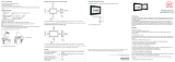
Fig. 13 Rear view of sensor with connectors
1 LWL-ST USB projecktor
2 LWL-ST camera A/1
3 LWL-ST camera A/2
4 LWL-ST camera B/1
5 LWL-ST camera B/2
6 NC
7 Power port (red)
5.2.2.2 Supply Voltage (Power)
Pin Signal
1
2
1 VCC
2 GND
Fig. 14 Pin assignment connector power port, see Fig. 13
Range: 18 V - 24 V (rated value 19 V) DC; maximum load 8 A
The cable shield is connected to the connector housing.
A 2-pin LEMO PushPull connector is used on sensor side.
i
For the power supply of the surfaceCONTROL 2500 sensor, only the supplied pow-
er supply is to be used.
5.2.2.3 Sensor Control (USB)
The sensor is configured and controlled via the available USB 2.0 interface.
On the PC side, a fiber-optic USB converter is used. It can be connected to a USB 2.0 or
USB 3.0 port.
The operation of the sensor via USB requires the installation of the corresponding driver
from the software CD.
Fig. 15 LWL USB converter
5.2.2.4 Image Data Transmission (Gigabit Ethernet)
On the PC side, a 2-port fiber-optic interface card is required.

Page 17
Installation
surfaceCONTROL 2500
5.2.3 Installation Instructions
surfaceCONTROL 2500 surfaceCONTROL 2500/ST
For all connection cables, use only the
appropriate cables from the accessories,
see A 1.1.
As connection cable, use fiber optics with
an OM class of at least OM2 or the corres-
ponding cables from the accessories, see
A 1.1.
Lay all connection cables in accordance with the generally applicable measuring tech-
nology regulations, i.e. for example not directly next to pulse-carrying lines, preferably
in a separate cable duct.
The minimum bending radii of the recommended cables for flexible laying must not be
less than 80 mm.
Only use the included power pack for the power supply of the sensor.
> Damage to or destruction of the sensor

Page 18
Operation of the Sensor
surfaceCONTROL 2500
6. Operation of the Sensor
6.1 Commissioning
Mount the sensor according to the assembly instructions, see 5.1.
Connect the sensor
- with the cables of the cable harness (surfaceCONTROL 2500).
- with fiber optic cables (surfaceCONTROL 2500/ST).
Connect the sensor to the PC and the power supply.
Switch on the power supply.
6.2 Displays
After getting ready for operation, switch on the external direct current power supply
(19 VDC).
The LEDs of the cameras now display different states by flashing, see 3.3. When using
DHCP to establish the network connection of the cameras, the sensor requires a few
seconds to one minute to be ready for operation.
i
The surfaceCONTROL 2500 and surfaceCONTROL 2500/ST sensor requires a
warm-up time of typically 30 minutes for high precision measurements.
6.3 Operating Programs
Various applications are provided for the operation of the sensor:
- surfaceCONTROL Defmap3D for individual surface analysis supports all measurement
tasks with surfaceCONTROL 2500 / surfaceCONTROL 2500/ST.
- surfaceCONTROL InspectionTools for automated inspection
- dimensionCONTROL CameraCalibration for sensor calibration
Depending on the characteristics of the measurement system, the corresponding CD,
incl. documentation, is supplied.
6.4 Installation
6.4.1 Requirements
The following minimum system requirements must be met for operating the surfaceCON-
TROL software packages:
- Windows 7 (32-bit and 64-bit), Windows 10 (32-bit and 64-bit)
- Intel Core-i5/Core-i7/Xeon
- 8 GB RAM
- Screen resolution: 1920 x 1080
The following procedure is necessary in order to install the software:
Install the hardware of the Ethernet interface(s) if not present.
Install the software and drivers according to the instructions on the CD.
Connect and license the USB dongle if available.
Connect the surfaceCONTROL 2500 / 2500/ST measurement system to the PC (Eth-
ernet, USB).

Page 19
Operation of the Sensor
surfaceCONTROL 2500
6.4.2 Connecting surfaceCONTROL 2500 / 2500/ST to the PC
Proceed as follows to connect surfaceCONTROL 2500 / 2500/ST via Ethernet and USB
to the PC:
surfaceCONTROL 2500 surfaceCONTROL 2500/ST
Complete the installation of the software.
Connect surfaceCONTROL 2500 to
the PC via the two Ethernet interfaces
and the USB interface and switch on
the power supply to the sensor.
Connect the surfaceCONTROL 2500/
ST to the PC via the fiber-optic Ether-
net interface and the fiber-optic USB
interface and switch on the power
supply to the sensor.
Wait until the surfaceCONTROL 2500 / 2500/ST measurement system is recognized
by the PC.
This may take a few seconds.
You can now operate the surfaceCONTROL measurement system with surfaceCONTROL
software packages.
6.4.3 Network
The cameras of the sensor are operated with a high data rate. Each camera fully utilizes
the available transfer capacity of the Gigabit Ethernet connection.
For correct operation of the sensor, the following recommendations should be taken into
account when selecting and configuring the network components.
6.4.3.1 Components
Due to the high data rate, a high-quality Gigabit Ethernet interface card is recommended,
for example Intel Pro/1000 PT. An independent Gigabit Ethernet interface must be avail-
able per camera. The use of a switch is not recommended.
The following network cards have been tested with the sensor:
Model Designation Standard Bus type
2500 Intel® PRO/1000 PT Dual Port Server Adapter
or
Intel® 1350-T2 Dual Port Server Adapter
2x 1000BASE-T PCIe
1.0 x4
2500/ST Intel® PRO/1000 PF Dual Port Server Adapter 2x 1000BASE-SX PCIe
2.1 x4
6.4.3.2 Design
Operating the cameras via Ethernet requires no additional driver installation. The neces-
sary performance drivers for the cameras are already installed with the software installa-
tion.
Note the following instructions when setting up the network:
- The cameras should be configured in a distinct network, separated from the Internet
or a local network (LAN).
- The mixed use of the network (e.g. with printer, Internet/e-mail, etc.) is possible in prin-
ciple, but can lead to loss of performance and data loss.
- Various network settings (e.g. firewall or packet filters) can interfere with communica-
tion with the cameras.

Page 20
Operation of the Sensor
surfaceCONTROL 2500
6.4.3.3 Configuration
The network card settings should be adjusted to improve system performance when
using Gigabit Ethernet cameras. Goal of the optimization is to minimize CPU usage and
to avoid packet loss.
Adjust the network card settings according to the following table:
Property Value
Packet size/maximum transmission unit (MTU) 8228 bytes or greater
Interrupt moderation Enable
Interrupt moderation rate Extreme
Receive buffer Maximum value configurable
Transmit buffer 256 bytes
The naming and setting options can vary depending on the network card used.
Standard packet size
The standard packet size of the cameras is 8228 bytes. The network card in the PC must
support at least this packet size to make use of the full performance capability of the
cameras.
Enabling jumbo frames
For optimal performance of the two cameras, jumbo frames should be enabled on the
network card. Depending on the manufacturer and type of the network card, the setting
is referred to as “Jumbo Frames” or “Jumbo Packets”. If this setting cannot be found, the
network card does not support this feature and should not be used with the sensor.
Proceed as follows to enable the jumbo frames:
Locate the network card used for the camera in the device manager or in a compa-
rable setting of your operating system.
Go to the settings of the network card.
Select the Jumbo Packet entry and set the value to 9014 bytes.
Confirm the change with OK.
i
After the change, an existing connection to the cameras is disconnected and re-
built.
6.5 Operating Information
6.5.1 Measuring Range
The measuring range of the sensors is factory-set. It is not possible to change the mea-
suring range by exchanging the lenses.
The area illuminated by the projector is relevant for the actual measuring range of the
sensor. The cameras are arranged in such a way that both cameras capture the area
illuminated by the projector within the complete measuring volume.
The measuring range in the Z-direction is trapezoidal due to the point-shaped light
source of the projector and the fan-out over the lens.
/