Assembly Instructions
colorCONTROL ACS
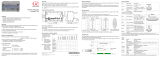
Functions
- Noncontact online color measurement
- Color recognition from a taught reference list
- Triggering, Synchronization
- Ethernet/EtherCAT, RS422, Digital I/O
- Measurement frequency up to 2000 Hz
Warnings
Connect the power supply in accordance to the safety regulations for electrical equipment. The
power supply may not exceed the specified limits.
> Danger of injury, damage to or destruction of the system
Protect the optical fiber ends from dirt and contamination, protect the cables from damage.
> Failure of the measurement device
Avoid shock and vibration to the controller or the sensor.
> Damage to or destruction of the system
Proper Environment
- Protection class: IP 40 (Controller)
IP 64 (Sensor)
- Operating temperature: 0 ... +45 °C (+32 ... +113 °F)
- Storage temperature: -20 ... 70 °C (-4 ... +158 °F)
More information about the system is available in the operating instructions. The instructions are
available online at: www.micro-epsilon.de/download/manuals/man--colorCONTROL-ACS7000--en.
pdf
Assembly
Place the controller on a level surface, or install it for example in a switch cabinet using a
DIN EN 60715 mounting rail (DIN rail TS35).
i
When attaching the controller, ensure that no connections, operating or display elements are
covered. Free space adjacent to the heat sink on the right side of the controller: min. 3 cm.
To remove the controller, push it upwards, and pull it forwards.
Dimensional Drawing Controller
120 (4.7)
211 (8.3)
123.8 (4.9)
(Feets can be removed)
76.2 (3.0)
81.2 (3.2)
appr.
63
DIN rail
fastener
R70
Connecting Sensor Cable to the Controller
i
When connecting the optical fibre connector, you need to ensure that the end points do not
touch any edges or surfaces to avoid damage.
Connect the sensor cable (thick strand, larger connector) to the controller.
Guide the coding keys upwards along the fiber connectors, until they fit into the controller’s
grooves. Carefully tighten the union nut by hand.
Connect the signal connector to the controller.
Angle Sensor Mounting
ACS1 30°/0°
Mount the sensor to the three
mounting holes. Use three
cylinder-head screws M4x45.
The receiver optics must be positi-
oned vertically above the measu-
rement object.
The optimum distance between
measurement object and sensor
is near the center of the working
range. Alternatively, use the
web interface (Video/Spectrum
program area) to set amplitude to
maximum.
68 ±1
(2.68 ±.04)
0
50 ±2
(1.97 ±.08)
17.5 ±0.5
(.69 ±.02)
24.5 ±0.5
(.96 ±.02)
99 ±1
(3.9 ±.04)
0
30°
Optimum
measurement
distance
Target
40
(1.57)
Bending radius
optical fiber
greater than 70 mm
20 (.79)
14 (.55)
40 (1.57)
63.5 (2.5)
5
(.2 dia.)
Dimensions in mm (inches), not to scale
MICRO-EPSILON Eltrotec GmbH
Manfred-Wörner-Straße 101
73037 Göppingen
www.micro-epsilon.com
X9771252-A051059HDR
*X9771252-A05*
Pin
Wire color
CAB-M9-7P-St-ge
Function
1
3
4
7
2
5
6
7-pol. male cable connector,
view: solder-pin side
1 white Out 1
2 brown Out 2
3 green Out 3
4 yellow Out 4
5 grey GND
Control Elements
1
2
3
4
5
7
8
9
10
6
1 On/off switch 7 Ethernet / EtherCAT
2 Pushbutton, LED Teach color 8 Light source
3 Pushbutton, LED White reference 9 Sensor connector
4 Pushbutton, LED Dark reference
1)
10 RS422, color, digital I/O and supply connectors
5 LED Measurement
1)
Set to factory setting: Press the pushbuttons
Dark reference and Teach color appr. 10 s.
6 LED Status
LED‘s
Power on Green Supply voltage OK
Status
(Ethernet)
Green No error, system ready
Red Error
Status
(EtherCAT)
If the EtherCAT interface is active, then the meaning of the Status-LED is
conform with the EtherCAT guidelines.
Measurement
Off No data transmission
Green Active data transmission
Red Error
Dark reference,
White reference,
Teach color
Green Action was successfully
Green, flashing Action is currently running
Red Action canceled incorrectly
Red
When pushbottons are pressed and the pushbot-
tons are locked
Ethernet, EtherCAT
Potential isolated RJ 45 standard connector for connecting the controller to an Ethernet network
(PC) or the EtherCAT bus system. The controller is connected with a PC or generally with a
network via the Ethernet interface. The internal websites can be accessed in the controller with a
web browser and so the controller can be operated.
Supply Voltage (Power)
Power connector, switch and LED on the controller
Use separate 24 V power supplies in automation systems for
measuring devices in drive units. MICRO-EPSILON recom-
mends using an optional available power supply unit PS2020.
Pin
Wire color
CAB-M9-4P-St-ge
Function
1
2
3
4
4-pol. male cable connector,
view: solder-pin side
1 white n.c.
2 brown + 24 VDC, ± 15 %, I
max
<1 A
3 black n.c.
4 blue GND (0V)
- gray n.c.
Digital I/O
A bridge between the pins 7 and 8 defines the logic levels for
all signals on the Digital I/O connector.
- Pin 7 and 8 connected: HLL (High logic level)
- Pin 7 and 8 open: LLL (Low logic level).
Digital I/O
on the controller
Pin
Wire color
CAB-M9-8P-St-ge
Function
1
3
4
7
2
8
5
6
8-pol. male cable connector,
view: solder-pin side
1 white Error
2 brown GND Error
3 green Sync. Out
4 yellow GND Sync. Out
5 grey Sync. In / Trig.
6 pink GND Sync In / Trig.
7 blue LLL / HLL
8 red LLL/ HLL
Color Switching Outputs (Color)
A bridge between the pins 7 and 8 of the Digital I/O con-
nector defines the logic level for the switching outputs.
- Pin 7 and 8 connected: HLL (High logic level)
- Pin 7 and 8 open: LLL (Low logic level).
Color switching
outputs on the
controller