Functions
The sensors of the CS series are non-contact infrared temperature sensors.
They calculate the surface temperature based on the emitted infrared energy
of objects.
Unpacking, Included in Delivery
- 1 Sensor thermoMETER CS
- 1 Connection cable
- 2 Mounting nuts
- 1 Assembly instructions
Warnings
Connect the power supply and the display/output device in accordance with
the safety regulations for electrical equipment.
> Risk of injury, damage to or destruction of the sensor
Avoid shocks and impacts to the sensor.
> Damage to or destruction of the sensor
The supply voltage must not exceed the specified limits.
> Damage to or destruction of the sensor
Protect the sensor cable against damage.
> Destruction of the sensor, failure of the measuring device
Do not kink the sensor cable and bend the sensor cable in tight radius. The
minimum bending radius is 14 mm (static). A dynamic movement is not
allowed.
> Damage to the sensor cable, failure of the measuring device
No solvent-based cleaning agents may have an effect on the sensor (neither
for the optics nor the housing)
> Damage to or destruction of the sensor
Notes on CE Marking
The following apply to the thermoMETER CS:
- EU Directive 2014/30/EU
- EU-Directive 2011/65/EU, “RoHS“
The measuring system is designed for use in industrial environments and
meets the requirements.
Technical Data
Ambient temperature -20 ... +80 °C (-4 ... +176 °F)
Storage temperature -40 ... +85 °C (-40 ... +185 °F)
Relative humidity 10 ... 95 %, non condensing
Dimensions M12x1, 85 mm long
Cable length 1 m (standard), 3 m, 8 m, 15 m
Output impedance min. 10 kΩ load impedance
Current draw 10 mA
Power supply 5 ... 30 VDC
Temperature range -40 ... 400 °C (scalable via software)
1
Spectral range 8 ... 14 µm
Optical resolution 15:1
Accuracy
2 3
± 1.5 °C or ± 1.5 % of reading
(whichever is greater)
Warm-up time 10 min
1) Optional up to 1030 °C
2) At ambient temperature 23 ± 5 °C and object temperatures > 0 °C
3) Accuracy for thermocouple output ±2.5 °C or ±1 %
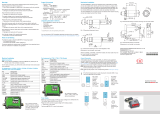
Optical Chart (15:1)
Mechanical Installation
The thermoMETER CS is equipped with a metric M12x1 thread and can be
installed either directly via the sensor thread or with the help of the both hex
nuts (standard) to the mounting bracket available.
Electrical Installation
i
Please use a stabilized power supply unit with an output voltage in
the range of 5 – 30 VDC which can supply 100 mA. The residual ripple
should be max. 200 mV.
Supply the thermoMETER CS either via USB or externally via power supp-
ly and not simultaneously!
i
- Use shielded cables only. The sensor shield has to be grounded.
- The shield (black) on the CS is not connected to GND (brown).
In any case it is necessary to connect the shield to ground or GND
(whichever works best)!
Analog Device
(mV Output on OUT Pin)
The output impedance must be ≥ 10 kΩ.
Analog Device
(Thermocouple Type K Output on OUT t/c K pins /only at Model CSTK Output
on OUT-Pin)
The output impedance must be ≥ 10 kΩ.
LED Functions
The green LED can be programmed for the following functions. For the
programming the USB adapter cable incl. software (option) is necessary. The
factory default setting for the LED is self diagnostic.
LED Alarm LED lights up if the object temperature ex-
ceeds or deceeds an alarm threshold.
Automatic aiming support Sighting feature for an accurate aiming of the
CS to hot or cold objects
Self diagnostic LED is indicating different states of the sensor.
Temperature code indi-
cation
Indication of the object temperature via the
LED
Off LED deactivated.
Factory Settings
The sensor is supplied with factory settings, see also the Chapter Factory
Settings in the Operating Instructions.
The default settings can be changed with the optional USB kit (USB adapter
cable + software).


