Page is loading ...

HME# 400G626
Rev B 1/14/10
DX100
Wireless Intercom
Operating Instructions


Table of Contents
SECTION 1. INTRODUCTION.......................................................................................................................1
EQUIPMENT IDENTIFICATION.......................................................................................................................2
MAIN EQUIPMENT FEATURES.......................................................................................................................3
Base Station Features ........................................................................................................................................3
Beltpac Features ................................................................................................................................................ 3
WH200 Headset Features..................................................................................................................................4
Speaker Station Features ...................................................................................................................................4
SECTION 2. EQUIPMENT SETUP.................................................................................................................5
BATTERY CHARGER SETUP ...........................................................................................................................5
Connect AC Power Supply................................................................................................................................5
Charge Batteries ................................................................................................................................................ 5
BASE STATION SETUP...................................................................................................................................... 6
Antenna and Power Setups................................................................................................................................6
Interference Avoidance......................................................................................................................................8
Multiple Base Stations.......................................................................................................................................9
Primary and Secondary Base Station Settings...................................................................................................9
Base Station Initialization................................................................................................................................10
BELTPAC / WH200 HEADSET / SPEAKER STATION SETUP AND REGISTRATION............................12
Set Up Beltpacs ...............................................................................................................................................12
Register Beltpacs............................................................................................................................................. 12
Set Up WH200 Headsets.................................................................................................................................14
Register WH200 Headsets............................................................................................................................... 14
Set Up Speaker Station.................................................................................................................................... 16
Register Speaker Station.................................................................................................................................. 18
SECTION 3. EQUIPMENT OPERATION...................................................................................................20
BASE STATION OPERATION ......................................................................................................................... 20
Controls and Indicators....................................................................................................................................20
Low Battery Indicator......................................................................................................................................20
BELTPAC OPERATION....................................................................................................................................21
WH200 HEADSET OPERATION......................................................................................................................23
SPEAKER STATION OPERATION.................................................................................................................. 25
SECTION 4. TROUBLESHOOTING............................................................................................................28
SECTION 5. TECHNICAL DATA.................................................................................................................29
EQUIPMENT SPECIFICATIONS .....................................................................................................................29
Base Station.....................................................................................................................................................29
Beltpac.............................................................................................................................................................30
WH200 Headset...............................................................................................................................................30
Speaker Station................................................................................................................................................30
Illustrations in this publication are approximate representations of the actual
equipment, and may not be exactly as the equipment appears.
HM Electronics, Inc. is not responsible for equipment malfunctions due to
erroneous translation of its publications from their original English version.
© 2010 HM Electronics, Inc.
The HME logo and product names are registered trademarks of HM Electronics, Inc. All rights reserved.

INFORMATION TO USER
This device complies with Part 15 of the FCC Rules. Operation is subject to the following two conditions: (1) This device may
not cause harmful interference, and (2) This device must accept any interference received, including interference that may cause
undesired operation.
This equipment has been tested and found to comply with the limits for Class B Digital Device, pursuant to Part 15
of the FCC Rules. These limits are designed to provide reasonable protection against harmful interference in a
residential installation. This equipment generates and can radiate radio frequency energy and, if not installed and
used in accordance with the instructions, may cause harmful interference to radio communications. However, there
is no guarantee that interference will not occur in a particular installation. If this equipment does cause harmful
interference to radio or television reception, which can be determined by turning the equipment off and on, the user is
encouraged to try to correct the interference by one or more of the following measures.
• Reorient or relocate the receiving antenna
• Increase the separation between the equipment and receiver
• Connect the equipment into an outlet on a circuit different from that to which the receiver is connected
• Consult the dealer or an experienced radio/TV technician for help
Any changes or modifications not expressly approved by the party responsible for compliance could void the user’s
authority to operate the equipment.
MANDATORY SAFETY INSTRUCTIONS
FOR INSTALLERS AND USERS
Use only manufacturer or dealer supplied antennas.
The Federal Communications Commission has adopted a safety standard for human exposure to RF (Radio Frequency)
energy, which is below the OSHA (Occupational Safety and Health Act) limits. These instructions also meet Industry
Canada RSS-GEN 7.14.
The term “IC:” before the certification number signifies that the Industry Canada technical specifications were met.
Base Station Antenna minimum safe distance: 7.9 inches (20 cm) at 100% duty cycle.
Base Station Antenna gain: This device has been designed to operate with an antenna having a maximum gain of up to
2dBi. The required antenna impedance is 50 Ohms.
Antenna mounting: The antenna(s) used for the base transmitter must be installed to provide a separation distance of at
least 7.9 inches (20 cm) from all persons and must not be co-located or operating in conjunction with any other antenna or
transmitter.
Antenna substitution: Do not substitute any antenna for the one supplied by the manufacturer or radio dealer. You may
be exposing person or persons to excess radio frequency radiation. You may contact your radio dealer or the manufacturer
for further instructions.
WARNING: Maintain a separation distance from the base station transmit antenna to a person(s) of at least 7.9 inches (20 cm)
at 100% duty cycle.
You, as the qualified end-user of this radio device must control the exposure conditions of bystanders to ensure the
minimum separation distance (above) is maintained between the antenna and nearby persons for satisfying RF exposure
compliance. The operation of this transmitter must satisfy the requirements of Occupational/Controlled Exposure
Environment, for work-related use. Transmit only when person(s) are at least the minimum distance from the properly
installed, externally mounted antenna.
Hereby, HM Electronics, Inc. declares that the DX100 is in compliance with the essential requirements and other relevant
provisions of R&TTE Directive 1999/5/EC.
This product operates in the 2400 to 2483.5 MHz frequency range. The use of this frequency range is not yet
harmonized between all countries. Some countries may restrict the use of a portion of this band or impose other
restriction relating to power level or use. You should contact your Spectrum authority to determine possible restrictions.

SECTION 1. INTRODUCTION
The DX100 provides private, secure communication. Each base station can have up to a total of fifteen BP200
Beltpacs, WH200 All-in-one Wireless Headsets and/or WS200 Wireless Speaker Stations “registered” to it. All
Beltpacs or all WH200 Headsets, or a combination of Beltpacs, Headsets and/or Speaker Stations can be used.
Four of the fifteen Beltpacs, Headsets and/or Speaker Stations can transmit at the same time.
Beltpacs/Headsets/Speaker Stations can be used either in the Push-To-Talk (PTT) or Hands-Free (HF) mode.
The base station operator can stop any Beltpac/Headset/Speaker Station from transmitting.
The MB100 Base Station and WS200 Speaker Station can be operated using standard AC electricity, an external
DC power source or six AA batteries. A power supply, cable and a battery sled are included with the base station.
This is an example of a typical theatrical application. A variety of other uses for the DX100 are possible.
1

EQUIPMENT IDENTIFICATION
The following equipment is standard with the DX100 Wireless Intercom System.
As you unpack the equipment, check the enclosed shipping documents to be sure you received all items listed.
2
WH200 All-in-one
Wireless Headset
AC40A
Battery Charger
Base Station Battery Sled
Base Station Antennas
(2 per Base Station)
MB100 Base Station
115/230 Volt AC Power Supply
(1 per Base Station, with Power Cord)
(1 per AC40A Battery Charger, with Power Cord)
BP200 Beltpac
HS15 Headse
t
Belt
p
ac Pouch
Battery
WS200
Wireless Speaker Station
WS200 Battery Sled
115/230 Volt AC Power Supply
with Power Cord for WS200
OPTIONAL EQUIPMENT
HS4-3 Earpiece & Lapel Microphone
HS15 Single-Muff Headset
HS15D Dual-Muff Headset
HS16 Lightweight Headset
HSI6000 Headset Adapter
XLR Headset Adapters:
MD-XLR4M Mini-DIN to 4-Pin Male
MD-XLR4F Mini-DIN to 4-Pin Female
MD-XLR5F Mini-DIN to 5-Pin Female
BAT850 Rechargeable Battery for WS200
AC850 Battery Charger for WS200

MAIN EQUIPMENT FEATURES
Base Station Features
1.
. RECEIVE indicator light
S display
utton
7. UN-LATCH button
8. CLR/BND (Clear/Band) button
partment cover
ent cover release latches
eltpac Features
3
POWER indicator light
2
3. RESET button
4. REGISTRATION STATU
5. PWR (Power) b
6. REG (Registration) button
9. Antennas
10. Power connector
11. Battery com
12. Battery compartm
B
. Headset cable connector
. Beltpac power and transmit lights
6. Volume-up S button
7. Volume-down T button
1
2
3. ISO (Isolate) button
4. IC (Intercom) button
5. PWR (Power) button
8. Battery
9. Battery release latch
8 9
2 3 4 2
1
5
6
7
1 2 3 4 5 6 7 8
9
10
11
12

4
H Features W 200 Headset
Power light
Transmit light
ercom) buttons
utton
5. Volume-up S button
6. Volume-down T button
peaker Station Features
5
3
1
6
2
8
7
9
1.
2.
3. IC1 & IC2 (Int
4. ISO (Isolate) b
7. Power button
8. Battery release latch
9. Battery
S
1. SIDE TONE adjustme (recessed)
Battery compartment cover
button and ligh
8. ISO (Isolate) button and light
11. Power supply cable connector
12. External speaker connector
nt
2.
3. Battery compartment cover release latches
4. HEADSET connector
5. POWER button and light
6. icrophone) CALL light and MIC (m
7. SPEAKER t
9. VOLUME down T and up S buttons
10. IC (Intercom) button and light
4
Left side
p
anel Front
p
anel Ri
g
ht side
p
anel
4
1
5
6
7
8 10 9 12 11
2
3

5
Charged batteries
in stora
g
e
p
orts
Battery in
char
g
in
g
p
or
t
Empty
char
g
in
g
p
orts
BATTERY CHARGER SETUP
IMPORTANT! – Before installing the system, connect the AC power supply to the AC40A Battery Charger
and plug it into an electrical outlet. Charge all the batteries while the other equipment is being installed.
Charging time is about 2.5 hours.
Connect AC Power Supply
• Attach the AC power supply cable connector to the screw connector on the battery charger.
• Plug the power cord connector into the AC power supply.
• Plug the power cord into an electrical outlet.
The red lights on the charger will come on and go off, and then the yellow lights will come on and stay on.
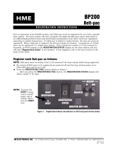
Charge Batteries
Up to four batteries can be charged in the battery charger at
the same time. The battery status lights next to each
charging port are explained below. Up to six fully charged
batteries can be stored in the battery storage ports.
• Insert a battery in each of four charging ports until it
clicks in place.
• A yellow light next to each charging port stays on while
the port is empty. When a battery is in a charging port, a
flashing yellow light next to it indicates CHARGE
PENDING, which means the battery is too hot. Adjust
the room temperature or move the charger to a cooler
area. When a battery is in a charging port, a yellow light
on steady next to it means CHARGE FAILED.
If this happens, follow the instructions on the side of
battery charger.
• A red CHARGING light next to a battery port stays on
while a battery in the port is charging.
A green READY light next to a battery port goes on
when a battery in the port is fully charged.
Store fully charged batteries in storage ports.
NOTE: The storage ports neither charge nor maintain the
batteries. They simply provide a place to store the
charged batteries until they are needed.
Batteries should not be left in charge ports after being fully
charged. If a battery is left in a charge port for more than
three weeks, the yellow indicator may light up. In this case, it does not indicate a faulty battery.
SECTION 2. EQUIPM
Power cord
connecto
ENT SETUP
r
AC
p
ower su
pp
l
y
Power cor
d
Power supply
cable connecto
r
AC40A Batter
y
Char
g
e
r
To electrical
outle
t

6
BASE STATI
Locate the two base station antennas and the AC power adapter and power cord received with the base station,
and connect them to the base station as described below.
ON SETUP
Antenna and Power Setups
Step 1. Connect the two enclosed
antennas to the antenna
connectors clockwise to tighten
Step 2. Note which of the following applies to you.
X100 with AC power wer supply
ower connector on to ble connector
clockwise to secure it to the base station. Plug the large female connector at one end of the AC
to the power supply. Plug the other end of the AC power cord into an electrical outlet.
connectors on the top and right
side of the base station, shown to
the right. Position the antennas
at right angles to each other.
The illustration below shows one
possible arrangement. Turn the
sleeve on each of the antenna
the antennas securely in position.
• If using the D
cable into the p
⎯ Plug the connector at the end of the AC po
p of the base station. Turn the sleeve on the ca
power cord in
Antenna
connectors
AC power supply
Powe
cord
le Power supply cab
Power supply
cable connector
Sleeve
Sleeves
r
Power
connector
POWER
light
PWR button
Antenna
Antenna

7
y power ⎯ Press in and up on the two battery cover release
th e
ent as shown below. An HME BAT850 Rechargeable NiMH Battery
will assure its
proper closing.
• If using the DX100 with an external DC power source ⎯ We recommend that you purchase a
rd such as the Radio Shack 12VDC, 5A cigarette lighter power adapter, PN 270-1558
w apter plug tip PN 273-1717. Follow the manufacturer’s instruc t the external
DC power source to the power connector on top of the DX100. Any power supply used with the
DX100 should be rated at least 12VDC, 500mA.
NOTE: Having a fully charged (or new) battery in its battery compartment when operating the DX100 with AC
or external DC power can prevent interruption of communication during a power outage, as the base
station will automatically switch to battery power.
• If using the DX100 with batter
latches to lift the cover and open the battery compartment.
Insert six AA batteries into
sled in the battery compartm
may be used instead.
e battery sled, in the positions shown inside the sled, and install th
Close the battery compartment by pressing its cover down until both latches snap in place.
NOTE: Pressing down on the cover next to both of the latches at the same time
power co
ith ad tions to connec
If only one base station will be used, skip pages 8 – 11 and go on to page 12.
If more than one base station will be used, continue with all the instructions on the following pages.
Battery cover
n
release latches
(Push latches i
direction of arrows
and fli
p
lid u
p
.
)
Battery sled
with batteries

8
REGISTRATION
STATUS display
Interf e
CLR/BND
button
REG
button
er nce Avoidance
Interference, ur whenever other equipment such as
WI-FI systems, wireless DMX systems, other HME Base Stations, etc. use the same frequency band. If these
systems can be limited to one portion of the band, then the DX100 can be set to the opposite half of the 2.4 GHz
to 2.48 GHz band. To avoid this type of interference, select the upper part of the frequency range on one Base
Station (or more), and the lower part of the frequency range on the other(s) as follows:
• Turn on the Bas
An “8” will a RATION STATUS display for a few seconds.
• After the
display i
base), press and hol
are still holding the CLR/BND button, press and hold the REG
button and wait until a L, H or A appears, and then release both
buttons.
• Press the CLR/BND button to cycle through parts of the
frequency band; L = Low end, H = High end and A = All.
• Wait until “c” appears on the display.
NOTE: Ba in the A (default) position.
“c e REGISTRATION STATUS display if you are setting the frequency
ban
If y
RE
If y station’s existing frequency band setting, you will have to re-register all beltpacs
d
which may be heard in a headset as popping sounds, may occ
“8” disappears and the REGISTRATION STATUS
s blank (primary base) or shows a double bar (secondary
d the CLR/BND button and then, while you
se stations are shipped
” will only appear on th
d the first time, or you are changing the setting.
ou stop at L, H or A that was already set, an “8” will appear for a few seconds and the
GISTRATION STATUS display will become blank.
ou change a base
e Station power.
ppear on the REGIST
an /or all-in-one headsets that were registered to that base station.

9
Multiple Base Stations
This mode of operation can be used to expand the number of users communicating through multiple HME Base
Stations operating in the same portion of the 2.4 GHz to 2.48 GHz frequency band.
Primary and Secondary Base Station Settings
One base station must be designated as “primary” and all others must be designated as “secondary”. You can have
only one primary and up to 3 secondary base stations. Secondary base stations are assigned numbers 1, 2, or 3.
• Label the base stations as “Primary,” “1,” “2” and “3.”
• Start with every base station and Beltpac/Headset power off.
Set DIP Switches
Open each secondary base station and set
DIP switch #4 to the ON position as follows.
• Using a T9 torque wrench, remove the
six screws from the front panel of each
secondary base station. Lift the front
panel carefully and set it face down.
Be careful not to pull any wires loose.
• Locate the DIP switch on the transceiver circuit board inside the front panel of each secondary base station.
Set DIP switch #4 to the ON position. Leave #s 1 and 3 in the OFF position.
• Replace the front panel and screws on the secondary base stations.
• The primary base station DIP switch #4 should be in the OFF position.
1
2
3
4
5
6
DIP switch inside
secondary
base station

10
REG
button
REGISTRATION
STATUS display
n
be set to this frequency
band before base station initialization is started. (See Interference Avoidance on page 8.)
ltpacs/Headsets/Speaker Stations as follows:
rimary Base Station ―
Turn the primary base station power on. Register any Beltpacs/Headsets/Speaker Stations to be used with the
primary base station (See pages 12 - 19). Turn each Beltpac/Headset/Speaker Station off after registering it.
Sec
•
ISTRATION STAT
the secondary base station is ready to be initialized.
Press the
REG button on the primary base st
The REGISTRATION STATUS display will show a small “o.”
To assign a number to a secondary base station and initialize it, press
e desired
ry base
itializes, the REGISTRATION STATUS display will continue
n of the secondary
ow one bar, to indicate the
condary has initialized to the primary.
The R
• Regi
• After ations registered to it.
• Repeat the above steps for each remaining secondary base station. Use a different number for each. Only the
primary base and the secondary base you are working with should have power on during initialization. All
other equipment should be off.
• After all secondary bases are initialized and Beltpacs/Headsets/Speaker Stations are registered, power-up all
base stations.
Base Station Initializatio
For multiple HME Base Stations to operate without interference, they must be properly initialized before
performing any other setups. After initializing each base station, register each Beltpacs/Headsets/Speaker
Station to that base according to the procedures on pages 12 - 19.
NOTE: Base stations must be set up for split-band operation prior to initialization. If a different frequency
band needs to be selected to avoid interference, the primary base station must
Initialize each base station and register all Be
P
•
ondary Base Stations ―
Power-on one secondary base station.
The REG US display will show a double bar
indicating
,
•
ation.
•
the
REG button on the secondary base. Pressing the button
causes it to cycle through the numbers 1, 2, and 3. When th
number appears, stop pressing and wait. While the seconda
in
sh
repeatedly
owing the selected number. When initializatio
base station is finished, the display will sh
se
• Press the
REG button on the primary base station.
EGISTRATION STATUS display will go blank.
ster Beltpacs/Headsets/Speaker Stations to the secondary (See pages 12 - 19).
registration, turn off the secondary base and all Beltpacs/Headsets/Speaker St

11
RESET
button
CLR/BND
button
RESET
button
ary base and let it recover.
me and
a time until they have all linked. Then do the next group. At this point all base stations and
d linked, ready for use.
Now proceed with normal system configuration, setting functions and levels as required.
ndary base ion, initialize the new secondary with the same nu ber
ou will have to register any Beltpacs/Headsets associated with the
ry base station, follow the preceding instructions completely.
stations, clear the previous secondary initialization as follows.
D button and e
holding the
SET button,
until the clear code “c” (lower case) appears on the
REGISTRATION
STATUS display.
after secondary base station initialization.
All Beltpacs/Headsets/ Speaker Stations associated with secondary
base stations also have to be registered again.
• If the primary base is shut down or if the prim wered off for mo
bases will drop their Beltpac/Headset/ Spea ions and begin searching for the primary. If the
primary is not found in 30 seconds, the second atically revert to primary-mode operation and
reconnect the Beltpacs/ Headsets/Speaker Stations. At this point the secondary REGISTRATION STATUS
displays will show three bars. If the primary is turned back on it will be necessary to press
the
RESET button on all secondary bases to allow them to find and initialize to the
primary again. It is therefore important to have all base stations connected to the same AC
circuit to prevent this situation when the system is shut down after hours and powered up
again the next day.
ode, and
secondary mode, the base cannot
recognize the Beltpacs/Headsets/Speaker Stations registered during primary operation. For secondary
bases, the Beltpacs/Headsets/Speaker Stations must always be registered after secondary base
initialization, with the primary base remaining active and the secondary base displaying one bar.
• Press the
RESET button on the prim
• Turn on the primary Beltpacs/ Headsets/Speaker Stations and let them link.
• Press the
RESET button on each secondary base station one at a ti
let it initialize to the primary base, as indicated by a single bar.
• Turn on the Beltpacs/Headsets/Speaker Stations associated with the secondary base stations. Do one group at
Beltpacs/Headsets/Speaker Stations should be powered-up an
•
• If it becomes necessary to replace a seco
as the old secondary. After initialization y
old secondary to the new secondary.
stat m
• If it becomes necessary to replace a prima
Before initialization of the secondary base
For each secondary, press the
CLR/BN
RESET button at the same time. Continue
CLR/BND button after you release the RE
th
Any Beltpacs/Headsets/Speaker Stations associated with the old
primary base station will have to be registered to the new primary,
ary base is po
ker Station connect
ary will autom
re than 30 seconds, all secondary
NOTE: You cannot register Beltpacs/Headsets/Speaker Stations to a base that is set to primary m
then switch the base mode to secondary for initialization. Once in

12
REGISTRATION
STATUS
REG
n
EADSET / SPE
h Beltpac, WH200 Headset and/or Speaker
electronic
replaced nce only 15
Beltpacs, Headsets and/or Speaker Stations can be in memory, whether currently in use or not, all memory must
BELTPAC / WH200 H AKER STATION
SETUP AND REGISTRATION
The first time you operate the DX100 system, you must register eac
Station for use with a specific base station. The base station will then recognize all registered Beltpacs/
Headsets/Speaker Stations when their power is on, and will know the difference between them and other
equipment operating on the same frequencies. If a Beltpac/Headset/Speaker Station is added,
or repaired later, the new one must be registered but the old one will remain in memory. Si
be cleared to remove any old Beltpac/Headset/Speaker Station registrations.
Set Up Beltpacs
display
butto
Before registering them, set up all Beltpacs as follows.
S
Ste
p
2
Ste
p
3
tep 1. Insert a fully charged battery in the
Beltpac, with the metal contacts on
rted first.
Step
ep
egister Beltpacs
Ste
p
1
the end of the battery inse
Press it in until it snaps.
2. Place the Beltpac in the pouch.
St 3. Plug the headset cable connector into the Beltpac.
R
Beltpacs must be within 6 feet (1.83 meters) of the base station while you a
station power is on, and each Beltpac you are going to register is turned
are already registered can be on or off.
TE: If you are setting up multiple base stations, the following steps m
registered to each base station.
1. Put the headset, of the Beltpac being registered, on your head.
Press the REG button on the front pa
re registering them. Be certain th
base off before you begin. Beltpacs
that
NO ust be repeated for Beltpacs being
Step
nel of the
base station.
NOTE: If you wait too long before going
and you will have to repeat Step 2.
rn
the unit on, then release theISO button. This will cause the Beltpac to enter the registration mode.
egin blinking red, then will blink green
two or three times and go off.
e
Step 2.
• The REGISTRATION STATUS display on
the base station will show a small “o” for open.
on to Step 3, the base station will
go out of the registration mode
Step 3. Press and hold the ISO button on the Beltpac while you press and release the PWR (power) button to tu
• The two power lights at the corners of the Beltpac near the IC
and ISO buttons will b
•
Wait! There may be a short delay.

I
13
REGISTRATION
STATUS
play
dis
CLR/BND
button
REGISTRATION
STATUS
display
RESET
button
BND button and the RESET button at the same time.
Continue holding the CLR/BND button after you
release the RESET button, until the clear code “c”
(lower case) appears on the REGISTRATION
STATUS display.
f registration is successfully completed:
ersion # registration, Registration
complete, …”
ill show the ID number assigned
to this Beltpac for about 10 seconds.
• in on steady green.
If r
A voice message in the headset will say “Power on, Beltpac #, Version #, Begin registration, …” Both
onds before you
t a
•
Clear all current registrations by pressing the CLR/
• A voice message in the headset will say “Power on, Beltpac #, V , Begin
• After a delay of up to 15 seconds, the REGISTRATION STATUS display w
NOTE: ID numbers are assigned sequentially as 0 thru 9, A, b, C, d and E.
The power light on the Beltpac, next to the IC button, will rema
• Repeat Steps 1 to 3 at the bottom of page 12 for each Beltpac to be registered.
egistration failed:
•
power lights on the Beltpac will be blinking red, and there may be a delay of up to 90 sec
hear “Registration failed.”
• Press the RESET button on the base station. When the REGISTRATION STATUS display becomes
blank, press the REG button on the base station and register the Beltpac again. If registration fails again,
call your dealer for assistance.
If you try to register more than 15 Beltpacs, Headsets and/or Speaker Stations
o base station
:
An F (for registration “Full”) will appear on the
REGISTRATION STATUS display on the base
station and you will hear “Registration failed” in the
headset.
•
• Register all active Beltpacs, one at a time.
Previously registered WH200 Headsets and Speaker Stations must also be re-registered.

14
REG
button
Set Up WH200 Headsets
B ach WH200
Headset, nserted first.
A voice message in the earpiece
will say “Headset #” and the power light on the opposite side of the earpiece will go on.
econds. A sage in ce will say
ide of the ear ill go off.
efore registering them, insert a fully charged battery in e
with the metal contacts on the end of the battery i
Press it in until it snaps.
Power On/Off
• To turn power on
Press and release the power button on the inside of the Headset housing.
• To turn power off
Press and hold the power button for approximately 3 s
“Headset off,” and the power light on the opposite s
REGISTRATION
STATUS
display
voice mes
piece w
the earpie
Power
Power
li
g
h
t
b
utton
Register WH200 Headsets
Headsets ) of the base station while you are registering them. Be certain the
ned off before you begin. Headsets
ting up multiple, daisy-chained base stations, the following steps must be repeated for
ation.
Step 1. Put
Step 2. Pres
base station.
• The REG
on the bas
.
Step 3. et while you press and release the power button to turn the unit
on, then release the ISO button. This will cause the Headset to enter the registration mode.
• The Headset power light will begin blinking red, then will blink green two or three times and go off.
Wait! There may be a short delay.
must be within 6 feet (1.83 meters
base station power is on, and each headset you are going to register is tur
that are already registered can be on or off.
NOTE: If you are set
WH200 Headsets being registered to each base st
the Headset on your head.
s the REG button on the front panel of the
ISTRATION STATUS display
e station will show a small “o”
for open.
NOTE: If you wait too long before
going on to Step 3, the base
station will go out of the
registration mode and you will
have to repeat Step 2
Press and hold the ISO button on the Heads

15
CLR/BND
button
REGIS
display
TRATION
TUS STA
RES
button
ET
REGISTRATION
TUS STA
display
d:
•
will be blinking red, and there may be a delay of up to 90 seconds before you
•
the base station and register the Headset again. If registration fails again,
call your dealer for assistance.
:
•
you will hear “Registration failed” in
the Headset.
•
lower case) appears on the
REGISTRATION STATUS display.
Register all active Headsets, one at a time.
Previously registered Beltpacs and Speaker Stations must also be re-registered.
If the registration is successfully complete
• A voice message in the Headset will say “Power on, Headset #, Version #, Begin registration, Registration
complete, …”
• After a delay of up to 15 seconds, the REGISTRATION STATUS display will show the ID number assigned
to this Headset for about 10 seconds.
NOTE: ID numbers are assigned sequentially as 0 thru 9, A, b, C, d and E.
• The power light on the Headset will remain on steady green.
• Repeat Steps 1 to 3 at the bottom of page 14 for each headset to be registered.
If registration failed:
A voice message in the Headset will say “Power on, Headset #, Version #, Begin registration, …” Both
power lights on the Headset
hear “Registration failed” and the REGISTRATION STATUS display goes blank.
Press the RESET button on the base station. When the REGISTRATION STATUS display becomes
blank, press the REG button on
If you try to register more than 15 Beltpacs, Headsets and/or Speaker Stations
a base stationto
An F (for registration “Full”) will appear on the
REGISTRATION STATUS display on the base
station and
Clear all current registrations by pressing the
CLR/BND button and the RESET button at the
same time. Continue holding the CLR/BND
button after you release the RESET button, until
the clear code “c” (
•

Set Up Speaker Station
The WS200 Speaker Station can be used together with Beltpacs and WH
wireless communication through its built-in microphone and speaker, or
also be connected to the un
200 All-in-one Headsets. It provides
a plug-in headset. A remote speaker can
it.
he Speaker Station can be used on a table top or mounted on the wall. It can be operated with standard AC power,
2-14VDC or with six AA batteries or an optional rechargeable battery. A power supply with cord and a battery
hether used on a table top or mounted on the wall, if AC operation is required, the Speaker
close enough to an electrical outlet to be reached with the power supply and cord.
on its left and right sides.
• Drill holes in the wall at the four marked spots, and
mount the WS200 over the holes with your selected
hardware (not provided).
AC Power Operation
If using the WS200 with AC power ―
• Plug the connector at the end of the power supply cord into the 12-14 VDC power connector on the
right side of the unit. Turn the sleeve on the connector clockwise to secure it to the unit.
• Plug the large female connector at one end of the AC power cord into the power supply. Plug the other
n electrical outlet.
T
1
sled are provided. W
Station must be located
Wall Mounting
1
2
3
4
• Hold the unit against the wall where you will mount it
and mark the wall through the four holes in the flanges
end of the AC power cord into a
Power supply cord
Power supply
AC power cord
H n ry compartment when operating the WS200 with AC or
ex n unication during a power outage. The WS200 will
autom
avi g a fully charged (or new) battery in its batte
ter al DC power can prevent interruption of comm
atically switch to battery power.
16
/