Page is loading ...


HM Electronics, Inc. is not responsible for equipment malfunctions due to erroneous
translation of its publications from their original English version.
Table of Contents
SECTION 1. INTRODUCTION .................................................................................................................... 1
EQUIPMENT IDENTIFICATION .................................................................................................................... 2
MAIN EQUIPMENT FEATURES .................................................................................................................... 3
Beltpac Features ............................................................................................................................................. 3
WH220 Headset Features ............................................................................................................................... 3
Base Station Features ..................................................................................................................................... 4
SECTION 2. EQUIPMENT SETUP .............................................................................................................. 5
AC40A BATTERY CHARGER SETUP ........................................................................................................... 5
Connect AC Power Supply ............................................................................................................................. 5
Charging the Batteries .................................................................................................................................... 5
AC50 BATTERY CHARGER SETUP .............................................................................................................. 6
Connect AC Power Supply ............................................................................................................................. 6
Charging the Batteries .................................................................................................................................... 6
BASE STATION SETUP ................................................................................................................................... 7
Equipment Connections .................................................................................................................................. 7
Interference Avoidance................................................................................................................................... 8
Multiple Base Stations .................................................................................................................................... 8
Primary and Secondary Base Station Settings ................................................................................................ 9
Base Station Initialization ............................................................................................................................... 9
BELTPAC / WH220 HEADSET SETUP AND REGISTRATION ..................................................................... 11
Set Up Beltpacs ............................................................................................................................................ 11
Register Beltpacs .......................................................................................................................................... 11
Set Up WH220 Headsets .............................................................................................................................. 13
Register WH220 Headsets ............................................................................................................................ 13
INTERCOM AND AUXILIARY EQUIPMENT SETUPS ............................................................................. 16
2-Wire Intercom ........................................................................................................................................... 16
4-Wire Intercom ........................................................................................................................................... 16
Auxiliary Equipment .................................................................................................................................... 17
8-Ohm Speaker ............................................................................................................................................. 17
SECTION 3. EQUIPMENT OPERATION ................................................................................................. 18
BASE STATION OPERATION ...................................................................................................................... 18
BELTPAC OPERATION ................................................................................................................................. 20
WH220 HEADSET OPERATION ................................................................................................................... 22
SECTION 4. ADAPTIVE FREQUENCY HOPPING ................................................................................ 24
Background .................................................................................................................................................. 24
CLEAR-COM Adaptive Frequency Hopping .............................................................................................. 24
Operation in Severe Environments ............................................................................................................... 25
Required AFH Equipment ............................................................................................................................ 25
Non-AFH Equipment ................................................................................................................................... 25
Interference Mitigation ................................................................................................................................. 26
SECTION 5. TROUBLESHOOTING ......................................................................................................... 27
SECTION 6. DX SERIES LED AID ............................................................................................................ 28
SECTION 7. TECHNICAL DATA .............................................................................................................. 31
EQUIPMENT SPECIFICATIONS .................................................................................................................. 31
Base Station .................................................................................................................................................. 31
Beltpac .......................................................................................................................................................... 32
WH220 Headset............................................................................................................................................ 32
BLOCK DIAGRAM ........................................................................................................................................ 33
DX200 Base Station ..................................................................................................................................... 33
© 2017 HM Electronics, Inc.
The HME logo and product names are registered trademarks of HM Electronics, Inc. All rights reserved.
Illustrations in this publication are approximate representations of the actual
equipment, and may not be exactly as the equipment appears.

Hereby, HM Electronics, Inc. declares that the DX200 is in compliance with the essential requirements and other
relevant provisions of R&TTE Directive 1999/5/EC.
This product operates in the 2400 to 2483.5 MHz frequency range. The use of this frequency range is not yet
harmonized between all countries. Some countries may restrict the use of a portion of this band or impose other
restriction relating to power level or use. You should contact your Spectrum authority to determine possible restrictions.
MANDATORY SAFETY INSTRUCTIONS
FOR INSTALLERS AND USERS
Use only manufacturer or dealer supplied antennas.
The Federal Communications Commission has adopted a safety standard for human exposure to RF (Radio
Frequency) energy, which is below the OSHA (Occupational Safety and Health Act) limits.
The term “IC:” before the certification/registration number only signifies that the Industry Canada technical
specifications were met.
Base Station Antenna minimum safe distance: 7.9 inches (20 cm) at 100% duty cycle.
Base Station Antenna gain: This device has been designed to operate with an antenna having a maximum
gain of up to 2dBi.
Antenna mounting: The antenna(s) used for the base transmitter must be installed to provide a separation
distance of at least 7.9 inches (20 cm) from all persons and must not be co-located or operating in conjunction
with any other antenna or transmitter.
Antenna substitution: Do not substitute any antenna for the one supplied by the manufacturer or radio dealer.
You may be exposing person or persons to excess radio frequency radiation. You may contact your radio
dealer or the manufacturer for further instructions.
WARNING: Maintain a separation distance from the base station transmit antenna to a person(s) of at least
7.9 inches (20 cm) at 100% duty cycle.
You, as the qualified end-user of this radio device must control the exposure conditions of bystanders to ensure
the minimum separation distance (above) is maintained between the antenna and nearby persons for satisfying
RF exposure compliance. The operation of this transmitter must satisfy the requirements of
Occupational/Controlled Exposure Environment, for work-related use. Transmit only when person(s) are at
least the minimum distance from the properly installed, externally mounted antenna.
FCC NOTICE
This device complies with Part 15 of the FCC rules. Operation is subject to the following two conditions:
(1) This device may not cause harmful interference, and (2) This device must accept any interference
received, including interference that may cause undesired operation.
This equipment has been tested and found to comply with the limits for a Class A digital device,
pursuant to Part 15 of the FCC rules. These limits are designed to provide reasonable protection against
harmful interference when the equipment is operated in a commercial environment. This equipment generates,
uses and can radiate radio frequency energy and, if not installed and used in accordance with the instruction
manual, may cause harmful interference to radio communication. Operation of this equipment in a residential
area is likely to cause harmful interference, in which case the user will be required to correct the interference
at his own expense.
Changes or modifications not expressly approved by HM Electronics, Inc. could void the users authority
to operate this equipment.

Waste Electrical and Electronic Equipment (WEEE)
The European Union (EU) WEEE Directive 2012/19/EU places an obligation on producers (manufacturers,
distributors and/or retailers) to take-back electronic products at the end of their useful life. The WEEE
Directive covers most HME products being sold into the EU as of August 13, 2005. Manufacturers, distributors
and retailers are obliged to finance the costs of recovery from municipal collection points, reuse, and recycling
of specified percentages per the WEEE requirements.
Instructions for Disposal of WEEE by Users in the European Union
The symbol shown below is on the product or on its packaging which indicates that this product was put on the
market after August 13, 2005 and must not be disposed of with other waste. Instead, it is the user’s
responsibility to dispose of the user’s waste equipment by handing it over to a designated collection point for
the recycling of WEEE. The separate collection and recycling of waste equipment at the time of disposal will
help to conserve natural resources and ensure that it is recycled in a manner that protects human health and the
environment. For more information about where you can drop off your waste equipment for recycling, please
contact your local authority, your household waste disposal service or the seller from whom you purchased the
product.
Korea: 해당 무선설비는 전파혼신 가능성이 있으므로 인명안전과 관련된 서비스는 할 수 없음
Singapore:
Taiwan:
注意!
依據低功率電波輻射性電機管理辦法第十二條經型式認證合格之低功率射頻電機,非經許可,
公司、商號或使用者均不得擅自變更頻率、加大功率或變更原設計之特性及功。
第十四條低功率射頻電機之使用不得影響飛航安全及干擾合法通信;經發現有干擾現象時,
應立即停用,並改善至無干擾時方得繼續使用。前項合法通信,指依電信規定作業之無線電信。
低功率射頻電機須忍受合法通信或工業、科學及醫療用電波輻射性電機設備之干擾。
Complies with
IDA Standards
DA10582

有毒有害物质或元素表
Table of Toxic and Hazardous Substances
部件名称
Names of Parts
有毒有害物质或元素
Toxic and Hazardous Substances or Elements
铅
Pb
镉
Cd
汞
Hg
六价铬
Cr6+
多溴联苯
PBB
多溴二苯醚
PBDE
BS200 基站
Top assembly BS200
(G27627-5Z1)
X
O
O
O
O
O
基站电路板
Audio PCB
(G27616-1)
X
O
O
O
O
O
收发器电路板
Front Panel PCB
(G26738)
X
O
O
O
O
O
收发器电路板
XCVR PCB
(G28842-1A1)
X
O
O
O
O
O
AC40 电池充电器
AC40
(G27368)
X
O
O
O
O
O
电源器
(453G008)
CCC P/S
X
O
O
O
O
O
O: 表示该有毒有害物质在该部件所有均质材料中的含量均在SJ/T11363-2006标准规定的限量要求以下。
O: Indicates that this toxic or hazardous substance contained in all of the homogeneous
materials for this part is below the limit requirements in SJ/T11363-2006
X: 该有毒有害物质至少在该部件的某一均质材料中的含量超出SJ/T11363-2006标准规定的限量要求。
X: Indicates that this toxic or hazardous substance contained in at least one of the homogeneous
materials used for this part is above the limit requirements in SJ/T11363-2006

有毒有害物质或元素表
Table of Toxic and Hazardous Substances
部件名称
Names of Parts
有毒有害物质或元素
Toxic and Hazardous Substances or Elements
铅
Pb
镉
Cd
汞
Hg
六价铬
Cr6+
多溴联苯
PBB
多溴二苯醚
PBDE
BP200 对讲机
Top Assembly BP200
(G26705-4Z1)
X
O
O
O
O
O
对讲机电路板
XCVR PCB
(G27560-1F1)
X
O
O
O
O
O
HS15 耳机
HS15/D Headset
(306G100-1 /306G101-1)
X
O
O
O
O
O
对讲机套
Pouch
(107G065)
O
O
O
O
O
O
电池
Battery
(104034)
O
O
O
O
O
O
O: 表示该有毒有害物质在该部件所有均质材料中的含量均在SJ/T11363-2006标准规定的限量要求以下。
O: Indicates that this toxic or hazardous substance contained in all of the homogeneous
materials for this part is below the limit requirements in SJ/T11363-2006
X: 该有毒有害物质至少在该部件的某一均质材料中的含量超出SJ/T11363-2006标准规定的限量要求。
X: Indicates that this toxic or hazardous substance contained in at least one of the homogeneous
materials used for this part is above the limit requirements in SJ/T11363-2006

表的有毒有害物质
Table of Toxic and Hazardous Substances
部件名称
Names of Parts
有毒有害物质或元素
Toxic and Hazardous Substances or Elements
铅
Pb
镉
Cd
汞
Hg
六价铬
Cr6+
多溴联苯
PBB
多溴二苯醚
PBDE
WH220 头佩戴式耳麦
Top Assembly WH220
(G27593-2Z1)
X
O
O
O
O
O
耳机电路板
PCB
(G28055-1D1)
X
O
O
O
O
O
电池
Battery
(104034)
O
O
O
O
O
O
O: 表示该有毒有害物质在该部件所有均质材料中的含量均在SJ/T11363-2006标准规定的限量要求以下。
O: Indicates that this toxic or hazardous substance contained in all of the homogeneous
materials for this part is below the limit requirements in SJ/T11363-2006
X: 该有毒有害物质至少在该部件的某一均质材料中的含量超出SJ/T11363-2006标准规定的限量要求。
X: Indicates that this toxic or hazardous substance contained in at least one of the homogeneous
materials used for this part is above the limit requirements in SJ/T11363-2006

1
The DX200 provides private, secure communication. Each base station can register up to fifteen BP200
Beltpacs and/or WH220 All-in-one Wireless Headsets. Any combination of Beltpacs and/or WH220 Headsets
can be registered. Four of the fifteen can transmit simultaneously. However, by connecting two or more base
stations together, these numbers can be increased. For example, two base stations can support thirty Beltpacs/
Headsets, of which eight can transmit simultaneously. Beltpacs or Headsets may be used either in the push-to-
talk or hands-free mode. The base station operator can stop all Beltpacs/Headsets from transmitting.
The DX200 can be used with RTS and Clear-Com cabled intercom systems. On the intercom channel, 2-wire
and 4-wire cabled intercoms may be operated simultaneously. Also, using the AUX In and AUX Out
connections, a second 4-wire intercom channel may be used.
A local headset can be used with the DX200. Using a local headset, the base station operator can talk to crew
members on the cabled intercom channel, Beltpacs/Headsets only, or all channels.
The BS200 Base Station can be operated using standard DC electricity or a vehicle electrical system for mobile
operation. A power supply and cable are included with the base station.
SECTION 1. INTRODUCTION

2
EQUIPMENT IDENTIFICATION
The following equipment is standard with the DX200 Wireless Intercom System.
As you unpack the equipment, check the enclosed shipping document to be sure you received all items listed.
Base Station Antennas
(2 per Base Station)
BS200 Base Station
BP200 Beltpac
CC-15-MD4 Headset
Beltpac Pouch
115/230 Volt AC Power Supply
(1 per Base Station, with Power Cord)
(1 per AC40A Battery Charger, with Power Cord)
OPTIONAL EQUIPMENT
HS4-3 Earpiece & Lapel Microphone
Disposable Earpiece Cover for HS15
Disposable Earpiece Cover for WH220
CC-15-MD Single-Muff Headset
CC-15-MD Dual-Muff Headset
HS16 Lightweight Headset
HSI6000 Headset Adapter
BAT41 Rechargeable Battery
XLR Headset Adapters:
o MD-XLR4M Mini-DIN to 4-Pin Male
o MD-XLR4F Mini-DIN to 4-Pin Female
o MD-XLR5F Mini-DIN to 5-Pin Female
AC40A
Battery Charger
WH220 All-in-one
Wireless Headset
BAT41 Battery

3
MAIN EQUIPMENT FEATURES
Beltpac Features
1. Headset cable connector
2. Beltpac power and transmit lights
3. ISO (Isolate) button
4. IC (Intercom) button
5. PWR (Power) button
6. Volume-up button
7. Volume-down button
8. Battery
9. Battery release latch
WH220 Headset Features
1. IC1 button
2. ISO (Isolate) button
3. Volume-up button
4. IC2 button
5. Volume-down button
6. Power/mode light
7. Microphone
8. Power button
9. Battery
10. Battery-release latch

4
Base Station Features
Front Panel
1. POWER switch
2. CLEAR/BAND button
3. STATUS display
4. UNLATCH button
5. IC (Intercom) receiver level control and
indicator light
6. ISO (Isolate) receiver level control and
indicator light
7. 2W and 4W indicator lights
8. SND and RCV (Send and Receive) controls
9. AUX IN and OUT (Auxiliary In and Out)
controls
10. LOCAL HEADSET VOLUME control
11. LOCAL HEADSET ISO indicator light
12. LOCAL HEADSET IC indicator light
13. LOCAL HEADSET MIC LEVEL control
14. LOCAL HEADSET TALK indicator light
15. LOCAL HEADSET cable connector
16. RESET button (recessed)
17. REGISTER button
18. 2W/4W button
19. 4W ONLY button
20. AUX IN button
21. ISO+ button
22. LOCAL HEADSET IC/ISO SELECT button
23. LOCAL HEADSET TALK button
Rear Panel
24. CLEAR-COM / RTS TW button
25. CH1/CH2 RTS channel select button
26. TERM OFF/TERM ON local termination
select button
27. 2-WIRE intercom connector (female)
28. NULL control
29. 2-WIRE intercom connector (male)
30. 4-WIRE connector
31. 0
o
ANTENNA connector
32. 90
o
ANTENNA connector
33. AUX IN connector
34. AUX OUT connector
35. 8-OHM SPKR 2-pin Phoenix connector
36. 12-14VDC Power connector
37. Chassis ground connector

5
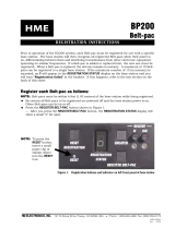
AC40A BATTERY CHARGER SETUP
The AC40A is the charger for Beltpac.
IMPORTANT! – Before installing the system, connect the AC power supply to the AC40A Battery Charger
and plug it into an electrical outlet. Charge all the batteries for the Beltpacs while the other equipment is being
installed. Charging time is about 2.5 hours.
Connect AC Power Supply
Attach the AC power supply cable connector to the screw connector on the battery charger.
Plug the power cord connector into the AC power supply.
Plug the power cord into an electrical outlet.
The red lights on the charger will come on and go off, and then the yellow lights will turn on and remain on.
Charging the Batteries
Up to four batteries can be charged simultaneously.
The battery status lights next to each charging port
are explained below.
Up to six fully charged batteries can be stored in the
battery storage ports.
Insert a battery in each of four charging ports
until it clicks in place.
A yellow light adjacent to each charging port
illuminates while the port is empty. When a
battery is in a charging port, an adjacent flashing
yellow light indicates CHARGE PENDING,
which indicates that the battery is too hot.
Adjust the room temperature or move the charger
to a cooler area. When a battery is in a charging
port, an adjacent, steady yellow light indicates
CHARGE FAILED. If this happens, follow the
instructions on the side of battery charger.
A red light adjacent to a battery port indicates
that the battery in the port is CHARGING. A
green light adjacent to an inserted battery
indicates a READY, fully charged battery.
Store the fully charged batteries in storage ports.
Batteries should not be left in charge ports after being
fully charged. A yellow light may illuminate if a
battery is left in a charge port for more than three
weeks. It does not indicate a faulty battery.
SECTION 2. EQUIPMENT SETUP
Charged batteries
in storage ports
Battery in
charging port
Empty
charging ports
Power cord
connector
AC power supply Power cord
Power supply
cable connector
AC40A Battery Charger
To electrical
outlet

6
AC50 BATTERY CHARGER SETUP
The AC50 is the charger for All-in-One headsets.
Before installing the system, connect the AC power supply to the battery charger and plug it into an electrical
outlet. Charge all the batteries while the other equipment is being installed. Charging time is about 2.5 hours.
Connect AC Power Supply
To connect the AC power supply to the battery charger:
1. Connect the AC power supply cable connector to the
power connection on the battery charger.
2. Connect the AC power cord to an electrical outlet.
The red lights on the charger will briefly display, and then the
yellow lights will appear and remain on.
Charging the Batteries
Up to four batteries can be charged in the battery charger at one time. The battery status lights next to each
charging port indicate the battery status. Up to four fully charged batteries can be stored in the battery Storage
ports. Insert a battery in each of four Charging ports until it clicks in place.
A yellow light next to a Charging port indicates that the port is EMPTY.
A red light next indicates that the battery port is CHARGING.
A green light indicates that the battery is READY.
A steady yellow light indicates that the CHARGE FAILED. If a charge fails, refer to the instructions
on the side of battery charger.
A flashing yellow light next
indicates CHARGE
PENDING, which means
the inserted battery is too
hot. Adjust the room
temperature or move the
charger to a cooler area.
Store fully charged batteries
in storage ports.
IMPORTANT: Batteries should not
be left in charge ports after being
fully charged. A battery left in a
charging port for more than three
weeks may display the yellow
indicator light, but it does not
indicate a faulty battery.

7
BASE STATION SETUP
The following description is for a basic, stand-alone DX200 system setup.
Connections and setup for multiple, daisy-chained base stations are described on pages 8 – 10.
Connections with 2-wire and 4-wire intercoms, and other auxiliary equipment are described in the INTERCOM
AND AUXILIARY EQUIPMENT SETUPS on pages 16 and 17.
Equipment Connections
Rear Panel
Front Panel
Step 1. Connect the two enclosed antennas to the antenna connectors (#31 and #32) on the rear panel of the base
station. Position the antenna at the 0° ANTENNA connector (#31) vertically. Position the antenna at the
90° ANTENNA connector (#32) horizontally, pointing to the left as indicated on the panel. Turn
(clockwise) the sleeve on each of the antenna connectors to tighten them securely in place.
Step 2. On the rear panel of the base station, plug the connector at the end of the AC power supply cord into the 12-
14VDC power connector (#36). Turn (clockwise) the nut on the cable connector to secure it to the base
station. Plug the large female connector of the AC power cord into the power supply. Plug the other end of
the AC power cord into an electrical outlet.
Step 3. Plug a headset into the HEADSET connector (#15) on the front panel of the base station.
Step 4. Press the POWER switch (#1) to turn on the base station. The red light on the switch should go on.

8
27 29
Interference Avoidance
Headset interference, sometimes heard popping sounds, may occur whenever other equipment such as WI-FI
systems, wireless DMX systems or other HME Base Stations use the same frequency band. If these systems
can be limited to one portion of the band, then the DX200 can be set to the opposite half of the 2.4 GHz to 2.48
GHz band. To avoid this type of interference, select the upper part of the frequency range on one Base Station
(or more), and the lower part of the frequency range on the other(s) as follows:
Step 1. Turn on the Base Station power. An “8” will appear on the STATUS display for a few seconds.
Step 2. After the “8” disappears and the STATUS display is blank (primary base) or if it displays a double bar
(secondary base), press and hold the CLEAR/BAND button. Then, while you are still holding the
CLEAR/BAND button, press and hold the REGISTER button and wait for a L, H or A to appear. Release
both buttons.
NOTE: Base stations are shipped in the A (default) position.
Step 3. Press the CLR/BND button to cycle through parts of the
frequency band; L = Low end, H = High end and A = All.
Step 4. Wait until “c” appears on the display.
Step 5. Initialize each Base Station and register all Beltpacs/Headsets to be used with each Base Station as
instructed on pages 11 – 14.
NOTE: “c” will only appear on the STATUS display if you are setting the frequency band the first time or
if you are changing the setting. If you stop at L, H or A that was already set, an “8” will appear for
a few seconds and the STATUS display will turn blank.
If you change a base station’s existing frequency band setting, you will have to re-register all
beltpacs and/or all-in-one headsets registered to that base station.
Multiple Base Stations
This mode of operation can be used to expand the number of users communicating through multiple HME Base
Stations operating in the same portion of the 2.4 GHz to 2.48 GHz frequency band. Two or more base stations
can be “daisy-chained” together with 2-wire connector cables (#27 and #29) on the rear panel of each base station
(following Clear-Com /RTS standards).
NOTE: The base station does not provide or require 2-wire line power.
The cable connectors must RTS Mode Clear-Com Mode
be 3-pin XLR type with the Pin 1 = Common Pin 1 = Common
following pin connections: Pin 2 = Channel 1 Pin 2 = N/C
Pin 3 = Channel 2 Pin 3 = Audio
If you are “daisy-chaining” multiple base stations:
Step 1. Press TERM button in (TERM ON) to terminate
the last base station in the daisy chain.
Be sure this is done to only one base station.
Step 2. For each base station, follow all the steps under
Equipment Connections on page 7.
Step 3. Follow the procedures on pages 9 and 10 to set
each base station as primary or secondary, select
frequency bands and initialize each base station.

9
Primary and Secondary Base Station Settings
One base station must be designated as “primary” while others are designated as “secondary”. You can have
one primary and up to three secondary base stations. Secondary base stations are assigned numbers 1, 2, or 3
during initialization to differentiate them in frequency offset.
Label the base stations as Primary, 1, 2 and 3.
Start with all base stations and Beltpac/Headsets powered off.
Configure each secondary base station as follows:
1. Remove the six screws from the top and three screws from each side of the top cover, and then remove and
set aside the cover.
2. Locate the DIP switch on the transceiver circuit board inside the base station. Set DIP switch #4 to the ON
position. Leave #s 1 and 3 in the OFF position.
3. Replace the cover and screws on the base station.
4. The primary base station DIP switch #4 should be in the OFF position.
Base Station Initialization
For multiple HME base stations to operate without interference, they must all be properly initialized before
performing other setups. After initializing each base station, register each Beltpacs/Headsets to be used with
that base according to the procedures on pages 11 - 14.
NOTE: Base stations must be set up for split-band operation prior to initialization. If a different frequency
band needs to be selected to avoid interference, the primary base station must be set to this
frequency band before base station initialization begins. (See Interference Avoidance on page 8.)
Initialize each base station and register all Beltpacs/Headsets as follows:
1. Power on the primary base station. Register any Beltpacs/Headsets to be used with the primary base station
(See pages 11 - 14). Turn off each Beltpac/Headset after it has been registered.
2. Power on one secondary base station. The STATUS display will show a double bar, indicating the
secondary base is ready to be initialized.
Base station ready to be initialized Small "o" indicates primary base
is open for registration
3. Press the REGISTER button on the primary base. The STATUS display will show a small “o”.
Small “o”
Double bar
DIP switch inside
secondary base station

10
4. To assign a number and initialize it to a secondary base station, press the REGISTER button on the secondary
base. Pressing the button repeatedly cycles through numbers 1, 2, and 3. When the desired number appears,
stop pressing and wait. During initialization, the STATUS display will continue showing the secondary
number. When initialization is completed, the display will show one bar, indicating that the secondary has
initialized to the primary.
5. Press the REGISTER button on the primary. The STATUS display will go blank.
6. Register Beltpacs/Headsets to the secondary (See pages 11 - 14). After registration, turn off the secondary
base and all Beltpacs/Headsets.
7. Repeat these steps for each remaining secondary base. Use a different number for each. Only the active
primary base and secondary base to be used should be powered on during initialization. All other equipment
should be turned off.
8. After all secondary bases are initialized and Beltpacs/Headsets are registered, power up all bases. Press reset
on the primary base and let it recover. Turn on the primary Beltpacs/Headsets, and let them link. Press the
reset on each secondary base (one at a time), and let it initialize to the primary (indicated by a single bar).
Turn on the Beltpacs/Headsets associated with the secondary bases one group at a time until they have all
linked. Follow with the next group. At this point, all bases and Beltpacs/Headsets should be powered up,
linked and ready for use.
9. Proceed with normal system configuration, setting functions and levels as required.
10. If it becomes necessary to replace a secondary base, use the procedure above to initialize the new secondary.
After initialization you will have to register any Beltpacs/Headsets associated with the old secondary to the
new secondary.
11. If it becomes necessary to replace a primary base, follow the above procedure completely. Before
initialization of the secondary bases, clear the previous secondary initialization as follows. For each
secondary, press the CLEAR/BAND button and the RESET button simultaneously. Continue holding the
CLEAR/BAND button after releasing the RESET button until the clear code “c” (lower case) appears on the
STATUS display. Any Beltpacs/Headsets associated with the old primary will have to be registered to the
new primary after secondary base initialization. All Beltpacs/Headsets associated with secondary base
stations also have to be registered again.
12. If the primary base is shut down or if the primary base is
powered off for more than 30 seconds, all secondary bases will
drop their Beltpac/Headset connections and begin searching for
the primary. If the primary is not found in 30 seconds, the
secondary will automatically revert to primary-mode operation
and reconnect the Beltpacs/ Headsets. At this point, the
secondary STATUS displays will show three bars. Once the
primary powered on, it will be necessary to press RESET on all
secondary bases to allow them to find and initialize to the
primary again. This makes it important that all bases be
connected to the same AC circuit to prevent this situation in the
event that the system is shut down at the end of a day and
powered up the next day.
NOTE: You cannot register Beltpacs/Headsets to a base that is set in primary mode, and then switch the
base mode to secondary for initialization. Once in secondary mode, the base cannot recognize the
Beltpacs/Headsets registered during primary operation. For secondary bases, the Beltpacs/Headsets
must always be registered after secondary base initialization, with the primary base remaining active
and the secondary base displaying one bar.
Three bars
Secondary base operating
in primary mode when no
primary base is found
One bar
Secondary is initialized to primary
Secondary base number
Secondary 2 searching for primary

11
17
3
BELTPAC / WH220 HEADSET SETUP AND REGISTRATION
The first time you operate the DX200 system, you must register each Beltpac and/or WH220 Headset for use
with a specific base station. The base station will then recognize all registered and powered on
Beltpacs/Headsets, and it will differentiate between them and other electronic equipment operating on the same
frequencies. If a Beltpac/Headset is added, replaced or repaired later, the new one must be registered and the
old one remains in memory. A maximum of 15 Beltpacs and/or Headsets can be registered to a single base
station at one time. If the maximum number of 15 is exceeded, you must clear all current registrations and re-
register all active Beltpacs/Headsets.
NOTE: The following two pages are for Beltpac setup and registration. WH220 Headset setup and
registration instructions are on pages 13 and 14.
Set Up Beltpacs
Before registration, set up all Beltpacs as follows.
Step 1. Insert a fully charged battery in the
Beltpac with the metal contacts on
the end of the battery inserted first.
Press it in until it snaps.
Step 2. Place the Beltpac in the pouch.
Step 3. Plug the headset cable connector into the Beltpac.
Register Beltpacs
Beltpacs must be within 6 feet (1.83 meters) of the base station during registration. Before you begin, be certain
the base station power is on and each Beltpac to register is turned off. Beltpacs that are already registered can
be turned on or off.
NOTE: If you are setting up multiple, daisy-chained base stations, the following steps must be repeated for
Beltpacs registration to each base station.
Step 1. Put the headset, of the Beltpac being registered, on your head.
Step 2. Press the REGISTER button on the front panel of the
base station (#17 on base station front panel illustration).
The STATUS display (#3 on base station front
panel illustration) will show a small “o” for open.
NOTE: If you wait too long before going on to Step 3,
the base station will go out of the registration
mode and you will have to repeat Step 2.
Step 3. Press and hold the ISO button on the Beltpac while you press and
release the PWR (power) button to turn the unit on, then release the
ISO button. This will cause the Beltpac to enter the registration mode.
The two power lights at the corners of the Beltpac near the IC
and ISO buttons will begin blinking red, then they will blink green
two or three times and turn off.
Wait! There may be a short delay.
Step 1
Step 2
Step 3

12
If registration is successfully completed:
A voice message in the headset will say “Power on, Beltpac #, Version #, Begin registration, Registration
complete, …”
After a delay of up to 15 seconds, the STATUS display will show the ID number assigned to this Beltpac for
about 10 seconds.
NOTE: ID numbers are assigned sequentially as 0 thru 9, A, b, C, d and E.
The power light on the Beltpac, next to the IC button, will remain on steady green.
Repeat Steps 1 to 3 on page 11 for each Beltpac to be registered.
If registration failed:
A voice message in the headset will say “Power on, Beltpac #, Version #, Begin registration, …” Both
power lights on the Beltpac will be blinking red, and there may be a delay of up to 90 seconds before you
hear “Registration failed” and the STATUS display goes blank.
Press RESET (#16) on the base station. To press RESET, insert a small paper clip or similar object into
the RESET hole at the lower-left corner of the base station front panel. When the STATUS display (#3)
goes blank, press the REGISTER button (#17) and register the Beltpac again. If registration fails again,
call your dealer for assistance.
If you try to register more than 15 Beltpacs and/or Headsets to a base station:
An F (for registration “Full”) will appear on the STATUS display (#3) on the base station, and you
will hear “Registration failed” in the Headset.
Clear all current registrations by pressing the CLEAR/BAND button (#2) and RESET (#16)
simultaneously. To press RESET, insert a small paper clip or similar object into the RESET hole at the
lower-left corner of the base station front panel. Continue holding the CLEAR/BAND button after you
release RESET, until the clear code “c” (lower case) appears on the STATUS display.
Register all active Beltpacs, one at a time. Previously registered Headsets must also be re-registered.
16 17
2 3
/