Page is loading ...

17329
Figure 4
Note: Adapter plate must be tight against shifter bracket.
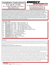
Set # 2.4108
Removal
Note: It is recommended that this set be professionally installed if
you are unfamiliar with this type of work, and a factory service
manual be purchased prior to performing any work on your vehicle
for proper disassembly, reassembly and torque specs. These
instructions are intended for bushing removal and install of Energy
Suspension polyurethane bushings, once you have removed the
factory component from your vehicle.
1. Fan shroud modification
Before beginning anything, first loosen the fan belt to
remove the fan from the water pump, then remove the
fan shroud. The fan shroud must be notched out to clear
the lower radiator hose and trans cooler lines (figure 1).
Drill new holes in the radiator 1” lower than the original
holes for fan clearance, using 1/4”drill bit (figure 2).
Note: For added clearance, reinstall the fan shroud after
the body mounts have been installed.
2. Shifter bracket modification
Next remove the transfer shifter bracket by removing
the 4 bolts underneath the carpet on the drivers side of
the transmission tunnel (figure 3). Remove the bracket
from underneath the vehicle. Remove the linkage
bushing bracket and drill out the holes to 5/16”.
Mount the supplied 1” drop adapter plate using the
supplied countersink bolts and lock nuts. Then remount
the linkage bushing bracket onto the adapter plate with
the supplied nuts and bolts (figure 4). Note: The shifter
bracket must be installed after body mounts are in place.
3.Body mount replacement
Note: Open the hood before jacking up the body and
remove the dipstick. Watch that wires, brake lines, fuel
lines and fuel filler hoses are not stretched. Next loosen
all body mount bolts and remove bolts from pos.#1 and
pos.#5 only (to keep from binding the body when
installing mounts on either side). Only raise the body
high enough to remove and replace the mounts. Install
the mounts one side at a time with the opposite side
loosened only. Refer to page 2 of the instructions for
proper placement of the bushings. You may need to file
the inside of the frame perch to remove any burrs before
installing the upper mounts. When jacking up the body
use a 2x4 or 4x4 for maximum support and weight
distribution (figure 5). Never place the jack directly on
body panels. Re-torque all the fasteners after all the
body mounts are in place and body is sitting on mounts.
Reinstall transfer shifter bracket with 1” adapter
plate (figure 6). Remove front body mount bumper
from under either side of front grill and install
supplied1” taller bumpers (figure 7). Recheck all areas
of vehicle worked on for proper clearances prior to use.
Example: fan clearance, brake lines, steering, wiring,
transfer operation, etc.
Figure 1
Figure 2
Page 1 of 2
Figure 3
97-00 Jeep 1” Lift Body Mount Instructions
3/JAN/14 BRH
1131 VIA CALLEJON, SAN CLEMENTE, CA 92673
R
Updated 8/JAN/03 BRH
2014 Energy Suspension. All rights reserved.
C
May not be reproduced, in any form, or by any means,
without the written consent of Energy Suspension.

Must reuse factory
washer/sleeve
Parts Diagram
Note: It is recommended
that you re-check all the
body mount fasteners
after 500 miles.
Figure 5
Figure 6
Figure 7
Parts List
Part Number
4189
4190
4187
4188
6184
15.03.49.39
15.03.83.39
15.05.63.39
15.03.09.39
15.03.04.39
15.05.09.39
15.05.62.42
15.10.439.39
15.08.80.39
15.05.61.39
15.05.61.39
15.07.20.40
15.07.20.40
15.03.74.40
15.03.81.39
17329
17330
Quantity
5
5
6
6
2
6
6
6
5
5
5
2
11
1
4
2
4
4
7
1
1
1
Position
1,5,6
1,5,6
2,3,4
2,3,4
Front Grill
2,3,4
2,3,4
2,3,4
1,5,6
1,5,6
1,5,6
Shift linkage
1,2,3,4,5,6
Shift linkage
Fan Shroud
Adapter Plate
Fan Shroud
Adapter Plate
Fan Shroud
Fan Shroud
Page 1
Page 2
Description
Body Mount, Upper
Body Mount, Lower
Body Mount, Upper
Body Mount, Lower
Front Body Mount Bumper
2 1/4” x 1/2” Flat Washer
1 1/16” x 1/2” Flat Washer
1/2-13 x 4 1/2” Bolt
2” x 7/16” Flat Washer
1 1/8” x 7/16” Flat Washer
7/16-14 x 4” Bolt
1/4-20 x 3/4” Flat Head Socket Screw
7/8” x 5/8” x 1” Spacer Sleeve
1” Adapter Plate
1/4-20 x 3/4” Bolt
1/4-20 x 3/4” Bolt
1/4-20 Nylon Lock nut
1/4-20 Nylon Lock nut
7/8” x 1/4” Flat Washer
1 1/4” x 1/4” Fender Washer
Instructions
Instructions
35
12
4
6
7
8
9
Position 1,5,6
1 Body
2 Factory washer/sleeve
3 4189 Upper
4 Frame
5 15.10.439.39
Spacer sleeve
7/8” x 5/8” x 1”
6 4190 Lower
7 15.03.09.39
2” x 7/16” Washer
8 15.03.04.39
1 1/8” x 7/16” Washer
9 15.05.09.39
7/16-14 x 4” Bolt
Position 2,3,4
1 Body
2 Factory washer/sleeve
3 4187 Upper
4 Frame
5 15.10.439.39
Spacer sleeve
7/8” x 5/8” x 1”
6 4188 Lower
7 15.03.49.39
2 1/4” x 1/2” Washer
8 15.03.83.39
1 1/16” x 1/2” Washer
9 15.05.63.39
1/2-13 x 4
Page 2 of 2
17330
Set # 2.4108
Updated 8/JAN/03 BRH
2014 Energy Suspension. All rights reserved.
C
May not be reproduced, in any form, or by any means,
without the written consent of Energy Suspension.
3/JAN/14 BRH
1131 VIA CALLEJON, SAN CLEMENTE, CA 92673
R Mount
Position
Diagram
1
2346
5
6184
/