Page is loading ...

Updated 8/JAN/03 BRH Updated 23/JAN/04 BRH
Updated 14/JAN/05 BRH Updated 10/JAN/06 BRH
Updated 2/JAN/07 BRH
2014 Energy Suspension. All rights reserved.
C
May not be reproduced, in any form, or by any means,
without the written consent of Energy Suspension.
Installation instructions
For set # 2.4109
07-11 Jeep Wrangler JK 4 Door
Body Mount Set
1131 VIA CALLEJON, SAN CLEMENTE, CA 92673
R
It is recommended that if you are unfamiliar with this type of work that you refer to a qualified service center specializing in this type of work.
It is also recommended that if you choose to do this work yourself that a factory service manual be obtained for the proper procedures
pertaining to removal, replacement and proper torque specifications for your vehicle. This instruction set is intended as a guideline for the
safe installation of Energy Suspension’s polyurethane bushings, once you have removed the factory components from your vehicle. Wheel
alignment is almost always disturbed when suspension components are removed or replaced. It is recommended that you have the
alignment checked on your vehicle at a qualified alignment shop. Visually inspect and re torque all fasteners after 200, 500 & 1000 miles,
Recheck fasteners during routine vehicle service. Energy Suspension recommends that you read over all the installation instructions and
check all P/N’s and quantities in the parts list before you start. Call customer service at 949-361-3935 if the parts in your kit do not match this
parts list. Prior to installation, make sure that your car is in excellent mechanical condition and that there are no suspension or steering
related problems. This part has been designed to work only with a car that is in good state of repair. No matter how carefully we design our
parts, this is one area we have no control over and cannot be held responsible.
Parts list: 2.4109
12 - 4301 (Lower mount POS 1. Upper mount POS 2 - 6).
12 - 4137 (Upper mount POS 1. Lower mount POS 2 - 6).
4 - 15.03.14.39 (2.50” x .500” x .125” Flat washer POS 1).
48 - 15.03.69.39 (.813” x .375” x .122” Flat washer ALL POS).
2 - 15.03.65.39 (1.00” x .500” x .195” Flat washer POS 1 TOP).
10 - 15.03.27.39 (2.50” x .500” x .187” Flat washer POS 2 - 6 TOP).
2 - 15.03.24.39 (2.50” x .625” x .187” Flat washer POS 6 (2008-11 ONLY).
24 - 15.05.13.38 (3/8-16” x 1-1/4” Bolt ALL POS).
2 - 15.05.89.40 (M12 x 1.75 x 100mm Bolt POS 1).
24 - 15.07.01.40 (3/8-16” Nylock nut ALL POS).
2 - 15.07.27.40 (M12 x 1.75 Flange locknut POS 1).
12 - 15.08.22.39 (Adapter plate ALL POS).
12 - 15.10.504.39 (.750” x .563” x 2.350” Sleeve).
1 - 17576 (this instruction sheet).
17576 Page 1 of 2 7/MAY/14 BRH ECN 14044
Grille Removal
Remove plastic retaining screws from top of radiator grille, be careful not to damage retainers as these will be reused. Remove plastic connector from
front turn signal bulbs by sliding the red locking tab to its unlocked position, then pressing on the plastic release lever on the back of the connector and
pulling away from bulb connection. Carefully, but with some force, pull the lower part of the plastic grille away from radiator cross member. Remove grille
completely from vehicle and set aside.
Body Mount Removal – Remove and Replace ONE side at a time!
Inside the engine compartment, driver side, unclip the O2 sensor connector located below the brake master cylinder from its mounting tab. Loosen all
M12 x 1.75 bolts that secure body to original mounts, but do not remove the M12 x 1.75 nut from front core position. Remove all M10 x 1.5 nuts that
secure original mounts to frame perches. Using car lift or floor jacks, support the body on the driver side. If the pinch seam is accessible for lifting from,
use two positions between the front and rear fender. If using floor jacks, or seams are obstructed, use a 2”X 4” wood block about 10” long on each jack
with each block positioned just inside the pinch seam. These blocks help spread the load when lifting the body above the frame.
Remove the body mount bolts on one side and lift body about 2”-3” above the original body mounts, lifting from both jacking points at the same time.
The original mounts should just be able to slide up and out of their frame perches. Using the diagrams on page 2, install the new polyurethane body
mounts at each position, taking note of the orientation and order. You may need to lift the body another inch or so to position the new mounts. After all
the new mounts are in their correct positions, evenly lower the body down onto the new mounts. Do not tighten any of the new nuts or bolts yet! Repeat
on the passenger side to install remainder of new body mounts. Once all new mounts have been positioned and the body resting on new mounts,
proceed to tighten the M12 x 1.75 bolts to the body to 80lb-ft (2008-11 POS 6 M14 x 2.0 bolts to the body to 80lb-ft) and then tighten the bolts that
secure the mounting plate to frame to 40lb-ft. Check all hard brake lines from the ABS Module to the frame rail in the engine compartment and make sure
the plastic clips holding them in place are not causing the lines to rub against each other. Reconnect O2 sensor to its mounting tab.

Updated 8/JAN/03 BRH Updated 23/JAN/04 BRH
Updated 14/JAN/05 BRH Updated 10/JAN/06 BRH
Updated 2/JAN/07 BRH
2014 Energy Suspension. All rights reserved.
C
May not be reproduced, in any form, or by any means,
without the written consent of Energy Suspension.
Installation instructions
For set # 2.4109
07-11 Jeep Wrangler JK 4 Door
Body Mount Set
1131 VIA CALLEJON, SAN CLEMENTE, CA 92673
R
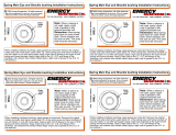
POS 1 POS 2, 3, 4, 5 & 6
15.05.89.39
15.03.65.39
15.03.14.39
15.03.14.39
4137
4137
15.05.13.39
15.05.13.39
15.03.69.39
15.07.01.40
15.03.27.39
4301
4301
15.07.27.40
15.08.22.39
Fits under
core support.
15.08.22.39
15.10.504.39
15.10.504.39
15.03.69.39
15.03.69.39
15.03.69.39
15.07.01.40
Factory
frame
perch
Factory
frame
perch
Factory
bolt & washer
17576 Page 2 of 2 7/MAY/14 BRH ECN 14044
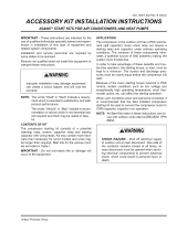
6
5
4
3
2
1
Front
Mount Position Diagram
(15.03.24.39
POS 6 (2008-11)
NOTE: 2008-11 POS 6 factory bolt & washer is an
M14 x 2.0. Use flat washer 15.03.24.39 on top of
mount 4301.
/